Sony/Philips Digital Interface Registers
A-92 ADSP-21368 SHARC Processor Hardware Reference
Receiver Control Register (DIRCTL)
This 32-bit read/write register is used to set up error control and sin-
gle-channel, double-frequency mode. The register is located at address
0x24A8. The register’s bits are shown in Figure A-34 and described in
Table A-38.
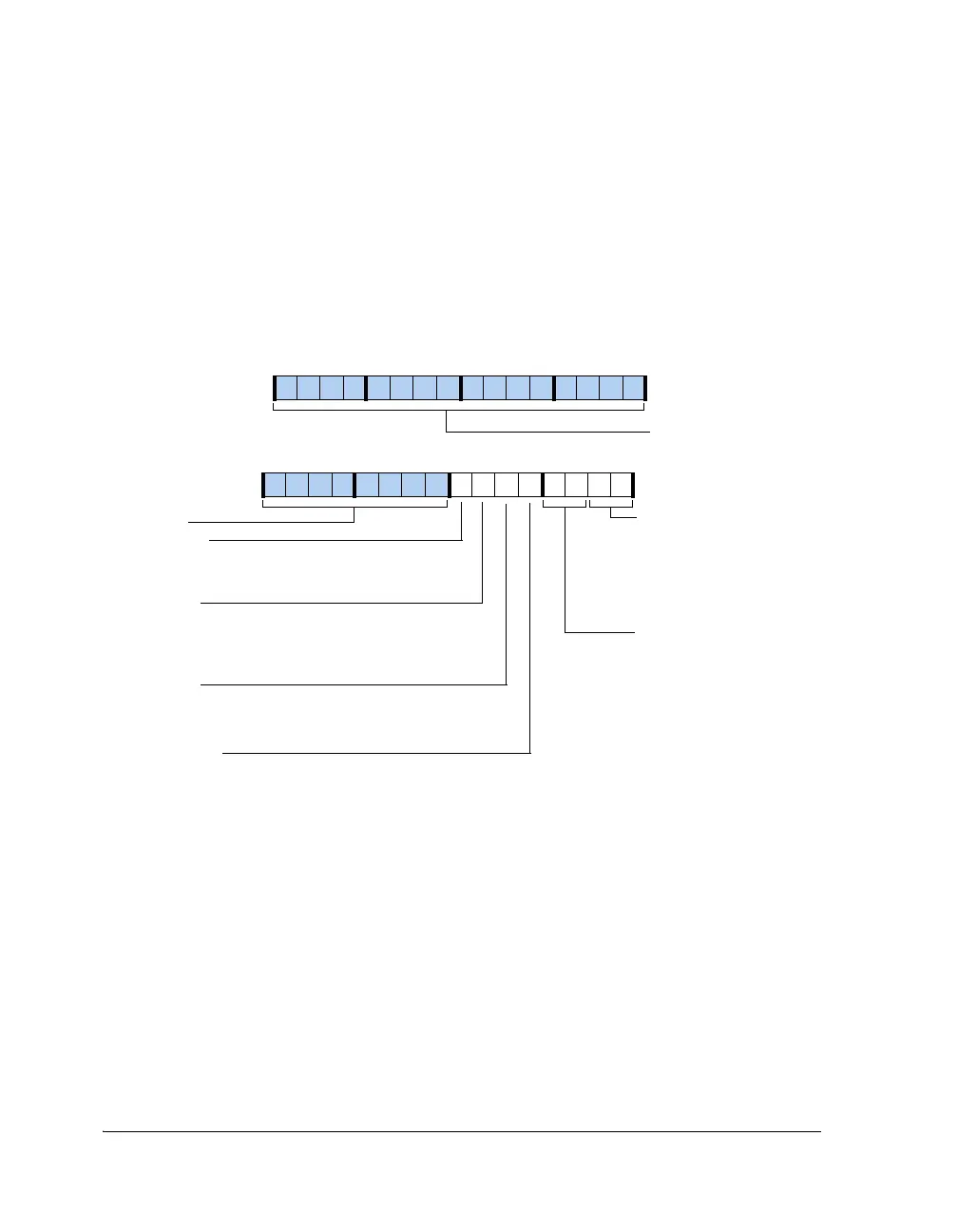
Figure A-34. DIRCTL Register
31 30 29 28 27 26 25 24 23 22 21 20 19 18 17 16
0000000000000000
DIR_BIPHASE
DIR_PLLDIS
Disable PLL
0=Use derived clock from the digital PLL
1=Use clock input from external PLL
Parity Biphase Error Control
00=No action taken
01=Hold last valid sample
10=Replace invalid sample with
zeros
11=Reserved
DIRCTL (0x24A8)
15 14 13 12 11 10 9 8 7 6 5 4 3 2 1 0
0000000000000000
Reserved
Reserved
DIR_LOCK
Lock Error Control
00=No action taken
01=Hold last valid sample
10=Send zeros after the last
valid sample
11=Soft mute of the last valid
audio sample is performed
DIR_MUTE
Mute
0=Mute disabled
1=Mute serial data outputs, maintaining
clocks (digital black)
DIR_SCDF
Single-Channel, Double-Frequency Mode Enable
0=2 channel mode disabled
1=2 channel mode enabled
DIR_SCDF_LR
Single-Channel, Double-Frequency Channel Select
0=Left channel
1=Right channel
 Loading...


