Serial Communications
11-2 ADSP-21368 SHARC Processor Hardware Reference
Serial Communications
The UART follows an asynchronous serial communication protocol with
these options:
• 5 – 8 data bits
• 1 or 2 stop bits
• None, even, or odd parity
• Baud rate = PCLK/(16 × divisor), where PCLK is the system clock fre-
quency and the divisor can be a value from 1 to 65,536
All data words require a start bit and at least one stop bit. With the
optional parity bit, this creates a 7- to 12-bit range for each word. The for-
mat of received and transmitted character frames is controlled by the line
control register (UARTxLCR). Data is always transmitted and received least
significant bit (LSB) first.
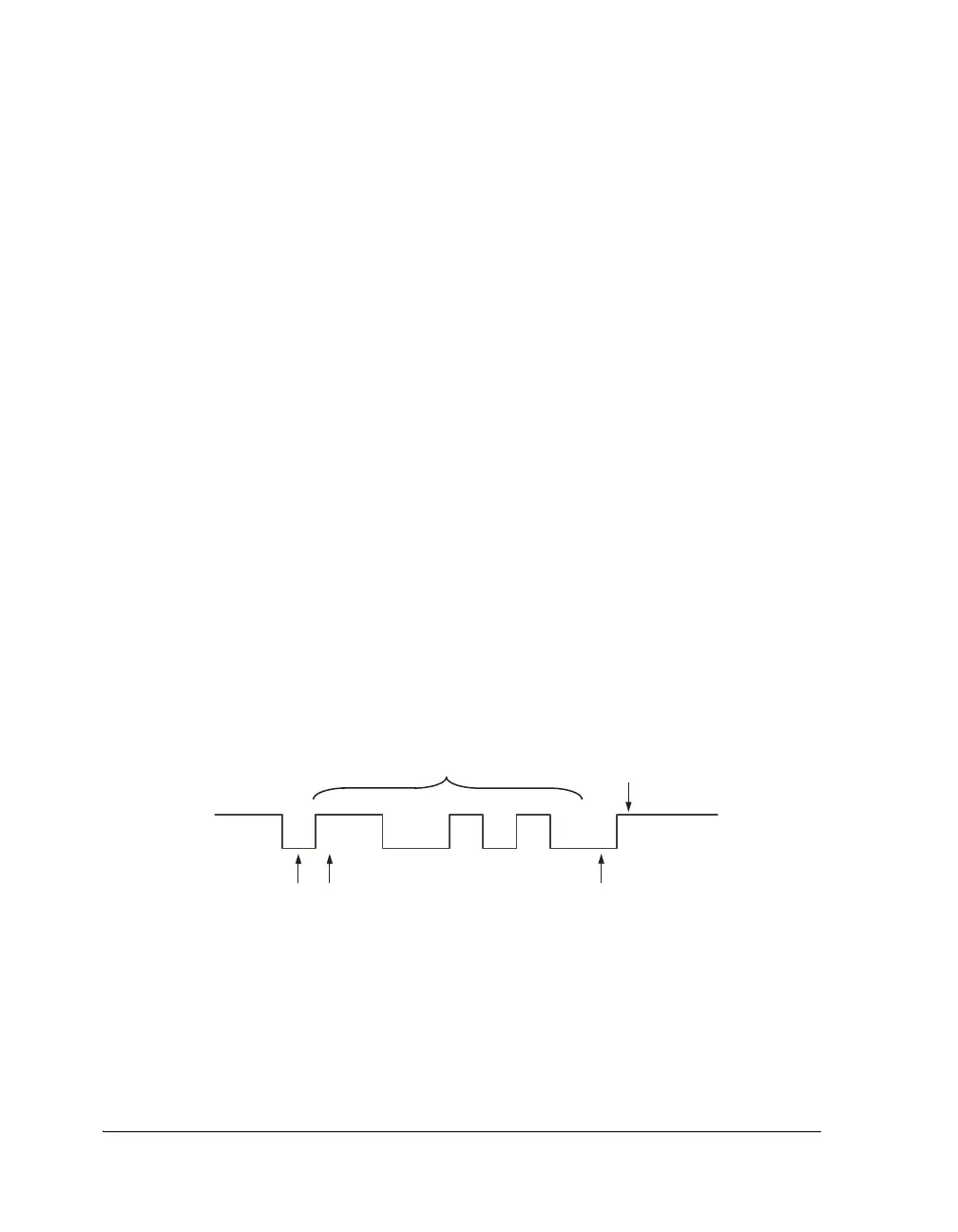
Figure 11-1 shows a typical physical bit stream measured on the transmit
pin.
Figure 11-1. Bit Stream on the Transmit Pin
DATA BITS
STOP BIT(S)
START BIT LSB
PARITY BIT (OPTIONAL, ODD OR EVEN)
D0 D1 D2 D3 D4 D5 D6 D7
 Loading...


