ADSP-21368 SHARC Processor Hardware Reference 10-15
Asynchronous Sample Rate Converter
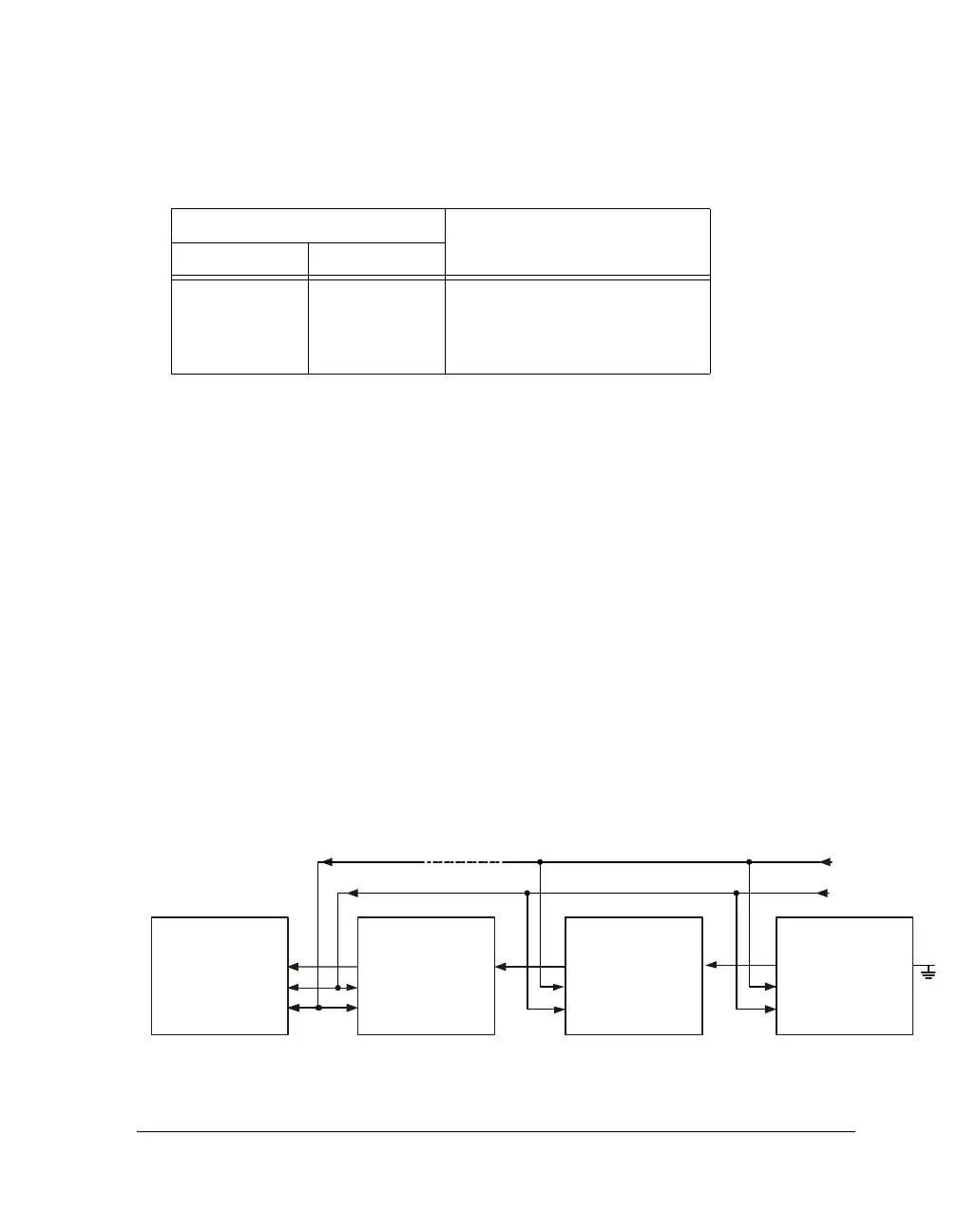
Time-Division Multiplex (TDM) Output Mode
In TDM output mode, several SRCs can be daisy-chained together and
connected to the serial input port of an ADSP-21367/8/9 and
ADSP-2137x processor or other processor (Figure 10-6). The SRC con-
tains a 64-bit parallel load shift register. When the
LRCLK_O pulse arrives,
each SRC parallel loads its left and right data into the 64-bit shift register.
The input to the shift register is connected to the TDM_IN signal, while the
output is connected to the SDATA_O signal. By connecting the SDATA_O sig-
nal to the TDM_IN signal of the next SRC, a large shift register is created,
which is clocked by the SCLK_O signal.
The number of SRCs that can be daisy-chained together is limited by the
maximum frequency of SCLK_O signals, which is about 25 MHz. For exam-
ple, if the output sample rate, f
S
, is 48 kHz, up to eight SRCs could be
connected since 512 × f
S
is less than 25 MHz.
Table 10-3. Word Width
SRCx_LENOUT_0:1
Interface Format
10
0
0
1
1
0
1
0
1
24 bits
20 bits
18 bits
16 bits
Figure 10-6. TDM Output Mode
SRCx
TDM_IN
SDATA_O
LRCLK_O
SCLK_O
ADSP-2136x
DR0
RFS0
RCLK 0
SCLK
LRCLK
SRCx
TDM_IN
SDATA_O
LRCLK_O
SCLK_O
SRCx
TDM_IN
SDATA_O
LRCLK_O
SCLK_O
 Loading...


