Input Data Port Registers
A-68 ADSP-21368 SHARC Processor Hardware Reference
Input Data Port Control Register 1 (IDP_CTL1)
Use the IDP_CTL1 register to configure and enable individual IDP chan-
nels. This register is shown in Figure A-28 and described in Table A-17.
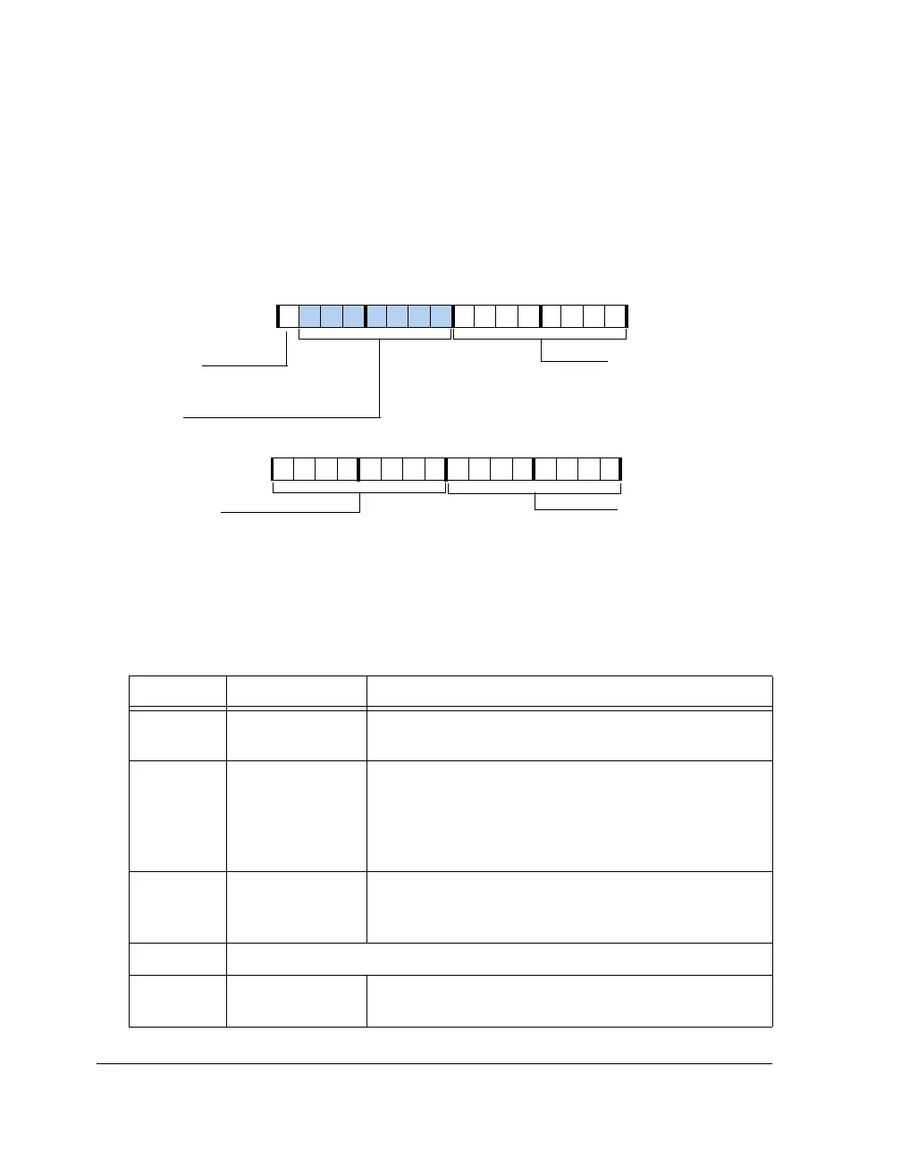
Figure A-28. IDP_CTL1 Register
Table A-17. IDP_CTL1 Register Bit Descriptions
Bit Name Description
7–0 IDP_ENx IDP Channel Enable. Enables individual IDP channels. Bit
0 enables channel 0, bit 1 enables channel 1, and so on.
15–8 IDP_DMA_ENx IDP DMA Enable. Enables standard DMA on all IDP
channels. Bit 8 enables channel 0, bit 9 enables channel 1,
and so on.
0 = DMA Disabled
1 = DMA Enabled
23–16 IDP_PINGx DMA Ping-Pong Enable. Enables ping-pong DMA on all
IDP channels. Bit 16 enables channel 0, bit 17 enables
channel 1 and so on.
30–24 Reserved
31 IDP_FFCLR Clear IDP FIFO. Setting this bit to 1 clears IDP FIFO.
This is a write-only bit and always returns 0 on reads.
31 30 29 28 27 26 25 24 23 22 21 20 19 18 17 16
0000000000000000
IDP_PINGx
IDP Channel x Ping-Pong
DMA Enable
1=Enable
0=Disable
Reserved
IDP_FFCLI
Clear IDP FIFO (WO)
1=Clear
15 14 13 12 11 10 8 7 6 5 4 3 2 1 0
0000000000000000
IDP_ENx
IDP Channel x Enable
1=Enable
0=Disable
9
IDP_CTL1 (0x24B2)
IDP_DMA_ENx
IDP Channel x DMA Enable
1=Enable
0=Disable
 Loading...


