Two Wire Interface Registers
A-136 ADSP-21368 SHARC Processor Hardware Reference
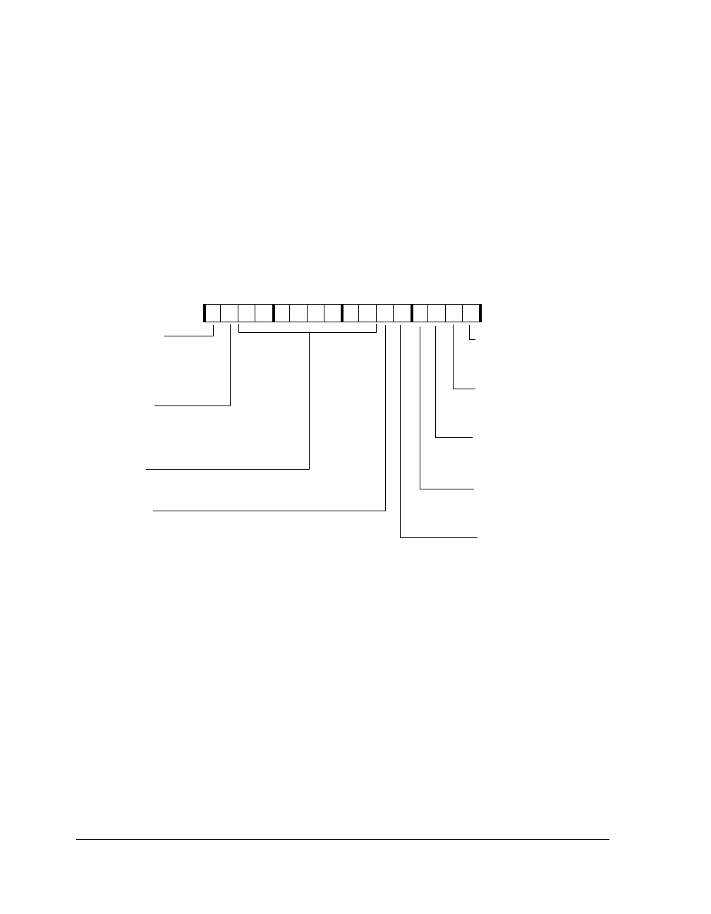
Master Control Register (TWIMCTL)
The TWI master mode control register (TWIMCTL, shown in Figure A-62
and described in Table A-57) controls the logic associated with master
mode operation. Bits in this register do not affect slave mode operation
and should not be modified to control slave mode functionality.
Figure A-62. Master Mode Control Register
15 14 13 12 11 10 9 8 7 6 5 4 3 2 1 0
0000000000000000
TWIMCTL (0x4414)
TWIMEN
TWIMDIR
TWISDAOVR
TWISCLOVR
TWIDCNT
TWIFAST
TWISTOP
TWIRSTART
TWIMLEN
Master Mode Enable
0=Master mode is disabled
1=Master mode is enabled
Master Address Length
0=Master address is 7-bit
1=Reserved
Master Transfer Direction
0=Transfer is master transmit
1=Transfer is master receive
Fast Mode
0=Standard mode timing
1=Fast mode timing
Issue Stop Condition
0=Normal transfer operation.
1=The transfer will conclude
as soon as possible
Serial Data Override
0=Normal serial data operation
1=Serial data output is driven to an active
“zero” level
Indicates the Number of Data
Bytes to Transfer
Repeat Start
0=Transfer concludes with a STOP condition
1=Issue a repeat START condition at the
conclusion of the current transfer
Serial Clock Override
0=Normal serial clock
operation
1=Serial clock output is driven
to an active “zero” level
 Loading...


