Making Connections in the SRUs
4-56 ADSP-21368 SHARC Processor Hardware Reference
Group B Connections—Pin Assignment Signals
Group B connections, shown in Figure 4-47 through Figure 4-49 and
Table 4-12, are used to route output signals to the 14 DPI pins.
01101 13 DPI_P12_O External pin 12
01110 14 DPI_P13_O External pin 13
01111 15 DPI_P14_O External pin 14
10000 16 TIMER0_O Timer0 output
10001 17 TIMER1_O Timer1 output
10010 18 TIMER2_O Timer2 output
10011 19 UART0_TX_O UART0 transmitter output
10100 20 UART1_TX_O UART1 transmitter output
10101-11111 21-31 RESERVED RESERVED
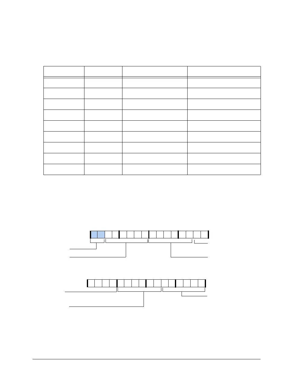
Figure 4-47. SRU2_PIN0 Register
Table 4-11. Group A Connections (Cont’d)
Binary Decimal Signal Description
31 30 29 28 27 26 25 24 23 22 21 20 19 18 17 16
1001100000000000
Reserved
15 14 13 12 11 10 9 8 7 6 5 4 3 2 1 0
0011101010101011
DPI_PB05_I
DPI pin buffer 5 Input
DPI_PB03_I
DPI Pin Buffer 3 Input
DPI_PB04_I
DPI Pin Buffer 4 Input
DPI_PB03_I
DPI_PB02_I
DPI Pin Buffer2 Input
DPI_PB01_I
DPI Pin Buffer 1 Input
SRU2_PIN0
(0x01C10)
DPI Pin Buffer 3 Input
Reset = 0x30017556
 Loading...


