SRC Operation
10-16 ADSP-21368 SHARC Processor Hardware Reference
TDM Input Mode
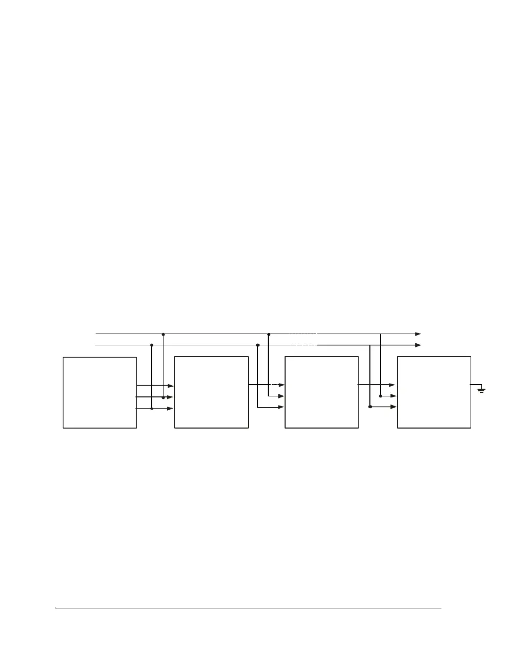
In TDM input mode, several SRCs can be daisy-chained together and
connected to the serial input port of an ADSP-21367/8/9 and
ADSP-2137x processor or other processor (Figure 10-7). The SRC con-
tains a 64-bit parallel load shift register. When the
LRCLK_I pulse arrives,
each SRC parallel loads its left and right data into the 64-bit shift register.
The input to the shift register is connected to the SDATA_IN, while the
output is connected to the TDM_I signal. By connecting the SDATA_I signal
to the TDM_I signal of the next SRC, a large shift register is created, which
is clocked by the SCLK_I signal.
The number of SRCs that can be daisy-chained together is limited by the
maximum frequency of the SCLK_O signal, which is about 25 MHz. For
example, if the output sample rate, f
S
, is 48 kHz, up to eight SRCs could
be connected since 512 × f
S
is less than 25 MHz.
Matched-Phase Mode
The matched-phase mode is the mode discussed in “Theory of Operation”
on page 10-2. This mode eliminates the phase mismatch between multiple
SRCs. The master SRC device transmits its f
S_OUT
/f
S_IN
ratio through
the
SDATA_O pin to the slave SRC’s TDM_IN pins. The slave SRCs receive
the transmitted f
S_OUT
/f
S_IN
ratio and use the transmitted f
S_OUT
/f
S_IN
ratio instead of their own internally-derived f
S_OUT
/f
S_IN
ratio as shown
Figure 10-7. TDM Input Mode
SRCx
SDATA_I
LRCLK_I
SCLK_I
ADSP-2136x
DR0
TF S 0
TCLK0
SRCx
TDM_OUT
SDATA_I
LRCLK_I
SCLK_I
SRCx
SDATA_I
LRCLK_I
SCLK_I
SCLK
LRCLK
TDM_OUT TDM_OUT
 Loading...


