ADSP-21368 SHARC Processor Hardware Reference 2-45
I/O Processor
DMA through the UART is started by setting up values in the DMA
parameter registers and then writing to the transmit and receive control
registers, enabling the module using the
UARTEN bits (in the UARTxTXCTL
and UARTxRXCTL registers) and enabling DMA using the UARTDEN bits. A
DMA can be interrupted by resetting the UARTDEN bit in the control regis-
ter. A DMA request that is already in the pipeline completes normally.
DMA chaining is enabled by setting the UARTCHEN bit in the transmit and
receive control registers. When chaining is enabled at the end of a current
DMA, the next set of DMA parameters are loaded from internal memory
and a new DMA starts. The index of the memory location is written in the
chain pointer register. DMA parameter values reside in consecutive mem-
ory locations as shown in Table 2-14. Chaining ends when the CP register
contains address 0x00000 for the next parameter block.
To start a DMA use the following steps.
1. Initialize index, modify, and count registers with the appropriate
values, keeping
DEN and EN bits disabled in the UARTxTX/RXCTL
register.
2. Write to the control register with the required control values and
set the DEN, EN and CHEN (if chaining is needed) bits.
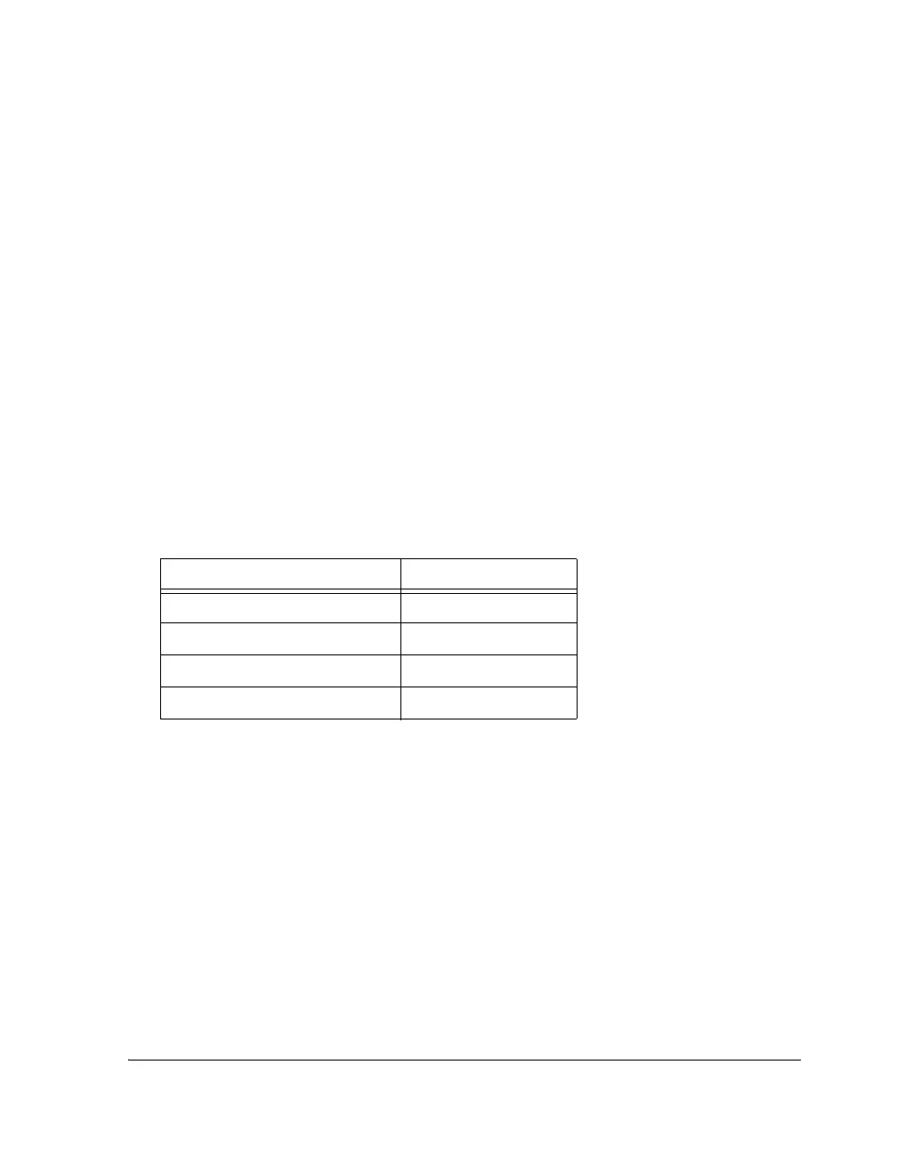
Table 2-14. Transfer Control Block Chain Loading Sequence
Address Register Value
CPUARTxTX/RX18–0 IIUARTxTX/RX
CPUARTxTX/RX18–0 – 0x1 IMUARTxTX/RX
CPUARTxTX/RX18–0 – 0x2 CUARTxTX/RX
CPUARTxTX/RX18–0 – 0x3 CPUARTxTX/RX
 Loading...


