Booting
14-38 ADSP-21368 SHARC Processor Hardware Reference
2. The DMA completes and the interrupt associated with the periph-
eral that the processor is booting from is activated. The processor
jumps to the applicable interrupt vector location and executes the
code located there. (Typically, the first instruction at the interrupt
vector is a return from interrupt (
RTI) instruction.)
3. The loader kernel executes a series of direct memory accesses
(DMAs) to import the rest of the application, overwriting itself
with the applications’ interrupt vector table (IVT).
4. After executing the kernel, the processor returns to location
0x90005 where normal program execution begins.
To support this process, a 256-word loader kernel and loader (which con-
verts executables into boot-loader images) are supplied with the
VisualDSP++ development tools for both SPI and external port booting.
For more information on the loader, see the tools documentation in
Related Documents on page xxxviii.
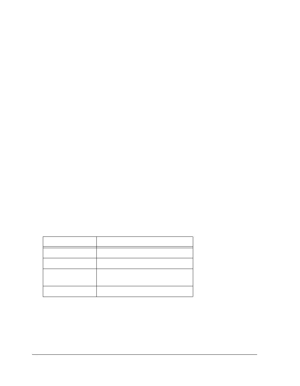
The boot source is determined by strapping the two BOOT_CFG1-0 pins to
either logic low or logic high. These settings are shown in Table 14-9.
Table 14-9. Booting Modes
BOOT_CFG1-0 Description
00 SPI Slave Boot
01 SPI Master Boot
10 EPROM/FLASH Boot Through The
External Port
11 Bypass Mode, Reserved
 Loading...


