ADSP-21368 SHARC Processor Hardware Reference 3-17
External Port
3B3SDBank 3 SDRAM.
1 = Bank 3 (MS3) connected to SDRAM
0 = Bank 3 (MS3) connected to asynchronous memory
0
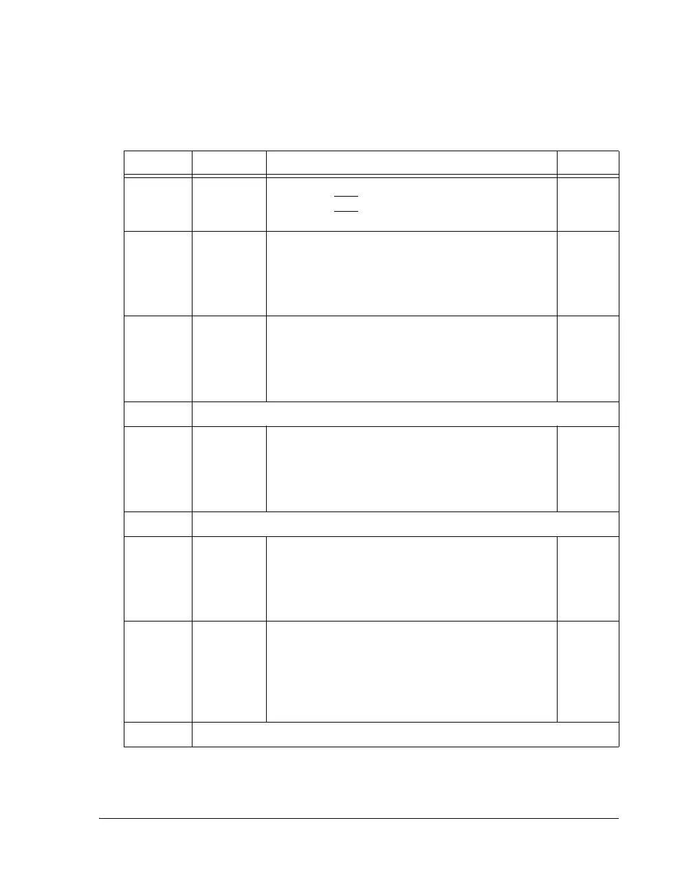
5–4 EPBR External Port Bus Priority.
11 = Rotating priority
10 = Core has high priority
01 = DMA has high priority
00 = Reserved
11
7–6 DMAPR DMA channel Priority for CH0 and CH1.
11 = Rotating priority
10 = Fixed priority
01 = Reserved
00 = Reserved
11
8Reserved
10–9 FRZDMA Arbitration Freezing Length for DMA.
0 = No freezing
1 = 4 Accesses
2 = 8 Accesses
3 = 16 Accesses
0
12–11 Reserved
14–13 FRZCR Arbitration Freezing Length for CORE Accesses.
0 = No freezing
1 = 4 Accesses
2 = 8 Accesses
3 = 16 Accesses
0
18–15 DATE DATA Enable. When the SDRAM/AMI memory con-
troller is in no pack mode, these bits of the data lane are
masked with zeros. The data lane is 8 bits. The 32-bit
data bus has four data lanes. DATA[31:0] is mapped to
DL3, DL2, DL1, DL0. For example, if DATE is 1010,
then DL3 and DL1 are masked with zeros.
0000
19 Reserved
Table 3-7. External Port Control Register Bit Descriptions (Cont’d)
Bit Name Description Default
 Loading...


