SPORT Control Registers and Data Buffers
5-70 ADSP-21368 SHARC Processor Hardware Reference
transmitters. The divisor is a 15-bit value, allowing a wide range of serial
clock rates. Use the following equation to calculate the serial clock
frequency:
The maximum serial clock frequency is equal to one-eighth the processor’s
internal clock (
CCLK) frequency, which occurs when CLKDIV is set to zero.
Use the following equation to determine the value of CLKDIV, given the
CCLK frequency and desired serial clock frequency:
The FSDIV bit field specifies how many transmit or receive clock cycles are
counted before a frame sync pulse is generated. In this way, a frame sync
can initiate periodic transfers. The counting of serial clock cycles applies
to internally- or externally-generated serial clocks. The formula for the
number of cycles between frame sync pulses is:
# of serial clocks between frame syncs = FSDIV + 1
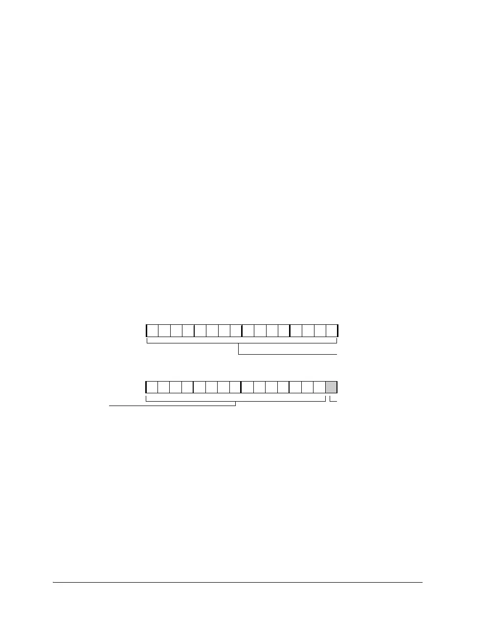
Figure 5-10. DIVx Register
f
SPORTx_CLK
f
CCLK
8CLKDIV 1+()
---------------------------------------
=
CLKDIV
f
CCLK
8 f
SPORTx_CLK
()
----------------------------------
1–=
31 30 29 28 27 26 24 23 22 21 20 19 18 17 16
0000000000000000
FSDIV
15 14 13 12 11 10 8 7 6 5 4 3 2 1 0
00 00000000000000
CLKDIV
Clock Divisor
25
9
Frame Sync Divisor
Reserved
DIV0 (0xC02)
DIV1 (0xC03)
DIV2 (0x402)
DIV3 (0x403)
DIV4 (0x4802)
DIV5 (0x4803)
 Loading...


