ADSP-21368 SHARC Processor Hardware Reference 10-5
Asynchronous Sample Rate Converter
In the frequency domain shown in Figure 10-3 on page 10-6, the interpo-
lation expands the frequency axis of the zero-order hold. The images from
the interpolation can be sufficiently attenuated by a good low-pass filter.
The images from the zero-order hold are now pushed by a factor of 2
20
closer to the infinite attenuation point of the zero-order hold, which is
f
S_IN
× 2
20
. The images at the zero-order hold are the determining factor
for the fidelity of the output at f
S_OUT
. The worst-case images that can be
computed from the zero-order hold frequency response are:
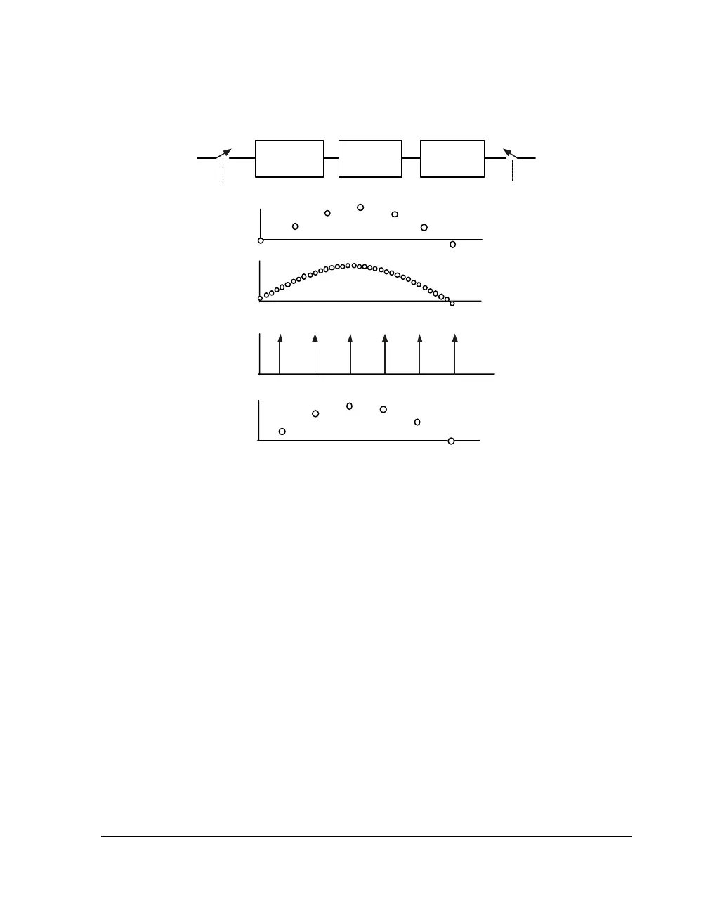
Figure 10-2. Time Domain of the Interpolation and Resampling
IN OUT
f
S_IN
f
S_OUT
TIME DOMAIN OF f
S_IN
SAMPLES
TIME DOMAIN OUTPUT OF THE LOW-PASS FILTER
TIME DOMAIN OF f
S_OUT
RESAMPLING
TIM
DOMAIN OF TH
Z
RO -O R D
RHOLDOUTPUT
INTERPOLATE
BY N
LOW-PASS
FILTER
ZERO-ORDER
HOLD
Maximum Image
π F×
f
S_INTERP
----------------------------
⎝⎠
⎛⎞
sin
π F×
f
S_INTERP
----------------------------
⎝⎠
⎛⎞
-----------------------------------------
=
 Loading...


