ADSP-21368 SHARC Processor Hardware Reference 13-11
Precision Clock Generators
frame sync C is specified in the
PWFSC bits (15–0) of the PCG_PW2 register
and the pulse width of frame sync D is specified in the PWFSD bits (31–16)
of the PCG_PW2 register.
If the pulse width is equal to 0 or if the divisor is even, then the actual
pulse width of the frame sync output is equal to:
If the pulse width is equal to 0 or if the divisor is odd, then the actual
pulse width of the frame sync output is equal to:
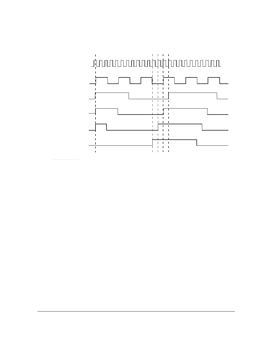
Figure 13-3. Phase Shift Settings
FRAME SYNC OUTPUT
(PHASE SHIFT = PERIOD -1)
CLOCK INPUT
(FOR BOTH CLOCK
AND FRAME SYNC)
ENABLE
FRAME SYNC OUT PUT
(P HASE SHIFT = 0 )
FRAME SYNC OUT PUT
(P HASE SHIFT = 1 )
CLOCK OUTPUT
FRAME SYNC OUT PUT
(P HASE SHIFT = 2 )
OTHER VALUES:
CLOCK DIVISOR = 4
FRAMESYNCDIVISOR= 16
PULSE WIDTH = 8
Pulse Width
FrameSyncDivisor
2
----------------------------------------------
=
Pulse Width
FrameSyncDivisor 1–
2
-------------------------------------------------------
=
 Loading...


