ADSP-21368 SHARC Processor Hardware Reference A-31
Register Reference
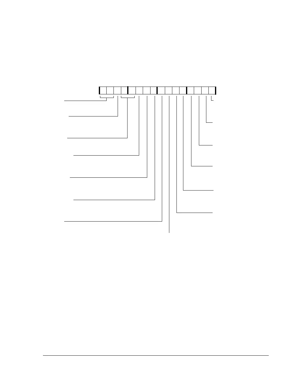
Figure A-13. SPCTLx Register (Bits 16–31) for Standard DSP Serial
Mode
31 30 29 28 27 26
24
23 22 21 20 19 18 17 16
0000000000000000
DXS_A
Data Buffer Channel A Status
11=Full, 10=Partially Full, 00=Empty
LFS
Active Low Frame Sync
1=Active low
0=Active high
DERR_A
Channel A Error Status (sticky)
SPTRAN=1 Transmit underflow status
SPTRAN=0 Receive overflow status
SDEN_A
DMA Channel A Enable
1=Enable
0=Disable
DXS_B
Data Buffer Channel B Status
11=Full, 10=Partially Full, 00=Empty
DERR_B
Channel B Error Status (sticky)
SPTRAN=1 Transmit underflow status
SPTRAN=0 Receive overflow status
SPTRAN
SPORT Data Direction
1=Transmit
0=Receive
SPEN_B
SPORT Enable B
1=Enable
0=Disable
BHD
Buffer Hang Disable
1=Ignore core hang
0=Core stall when TXSPx full or RXSPx empty
LAFS
Late Frame Sync
1=Late frame sync
0=Early frame sync
SCHEN_A
DMA Channel A
Chaining Enable
1=Enable
0=Disable
SDEN_B
DMA Channel B Enable
1=Enable
0=Disable
SCHEN_B
DMA Channel B
Chaining Enable
1=Enable
0=Disable
25
FS_BOTH
Frame Sync Both
1=Issue word select if data is present in both
TXSPxy and RXSPxy
0=Issue word select if data is present in either of
TXSPxy or RXSPxy buffers
SPCTL0 (0xC00) SPCTL1 (0xC01)
SPCTL2 (0x400) SPCTL3 (0x401)
SPCTL4 (0x800) SPCTL5 (0x800)
SPCTL6 (0x4800) SPCTL7 (0x4801)
 Loading...


