Serial Port Registers
A-30 ADSP-21368 SHARC Processor Hardware Reference
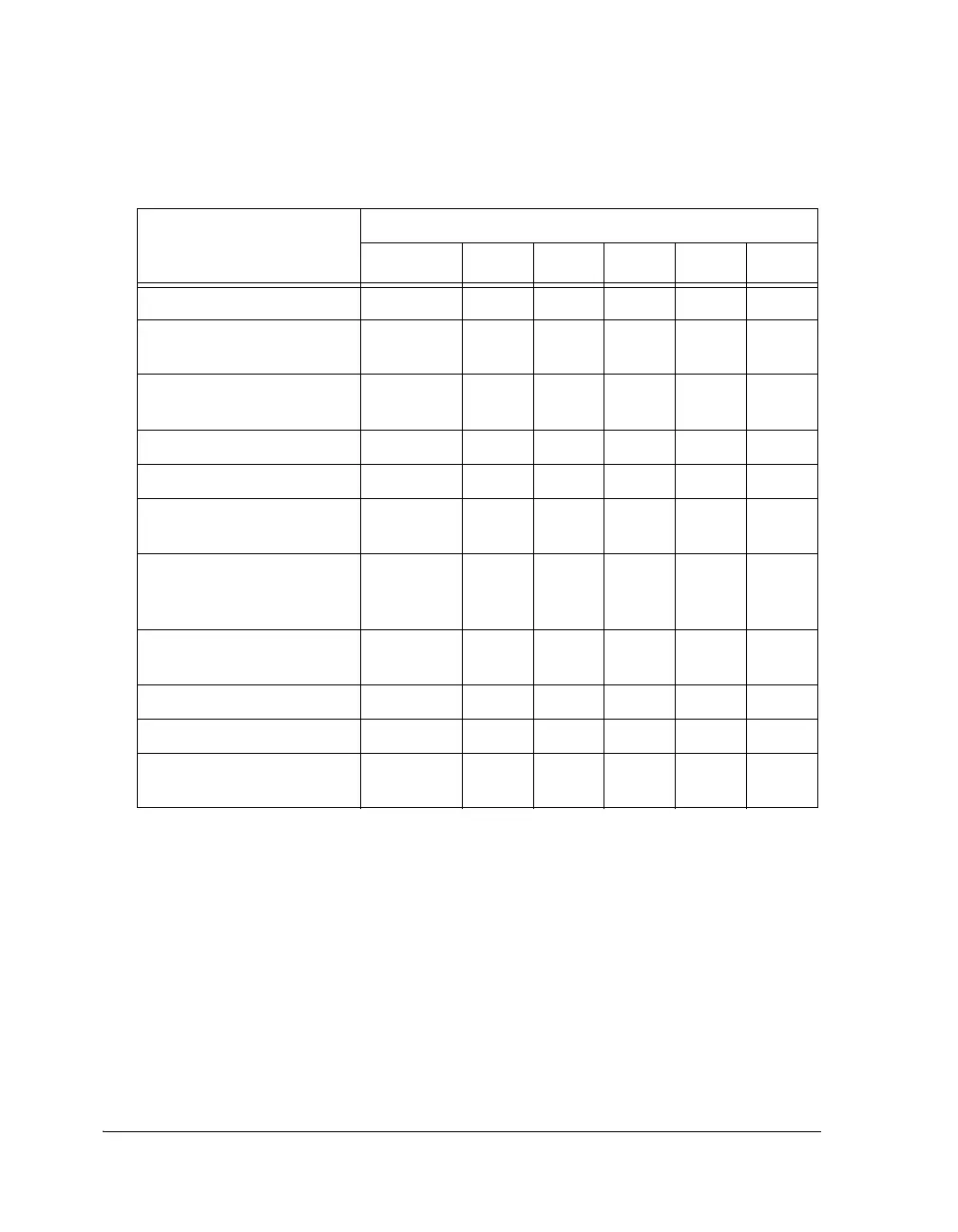
Table A-7. SPORT Operation Modes
Operating Modes
Bits
OPMODE LAFS FRFS MCEA MCEB SLENx
Standard DSP Serial Mode 0 0, 1 X 0 0 3-32
1
I
2
S (Tx/Rx on Left Channel
First)
1 0 1 0 0 8-32
I
2
S (Tx/Rx on Right Channel
First)
1 0 0 0 0 8-32
Packed I
2
S Mode A Channel1 0X103-32
Packed I
2
S Mode B Channel1 0X013-32
Packed I
2
S Mode A and B
Channels
1 0 X 1 1 3-32
Left-Justified Sample Pair
Mode
(Tx/Rx on FS Rising Edge)
1 1 0 0 0 8-32
Left-Justified Sample Pair
(Tx/Rx on FS Falling Edge)
1 1 1 0 0 8-32
Multichannel A Channels 0 0 X 1 0 3-32
1
Multichannel B Channels 0 0 X 0 1 3-32
1
Multichannel A and B
Channels
0 0 X 1 1 3-32
1
1 Although serial ports process word lengths of 3 to 32 bits, transmitting or receiving words small-
er than 7 bits at core clock frequency/4 of the processor may cause incorrect operation when
DMA chaining is enabled. Chaining disables the processor’s internal I/O bus for several cycles
while the new transfer control block (TCB) parameters are being loaded. Receive data may be
lost (for example, overwritten) during this period.
 Loading...


