ADSP-21368 SHARC Processor Hardware Reference A-87
Register Reference
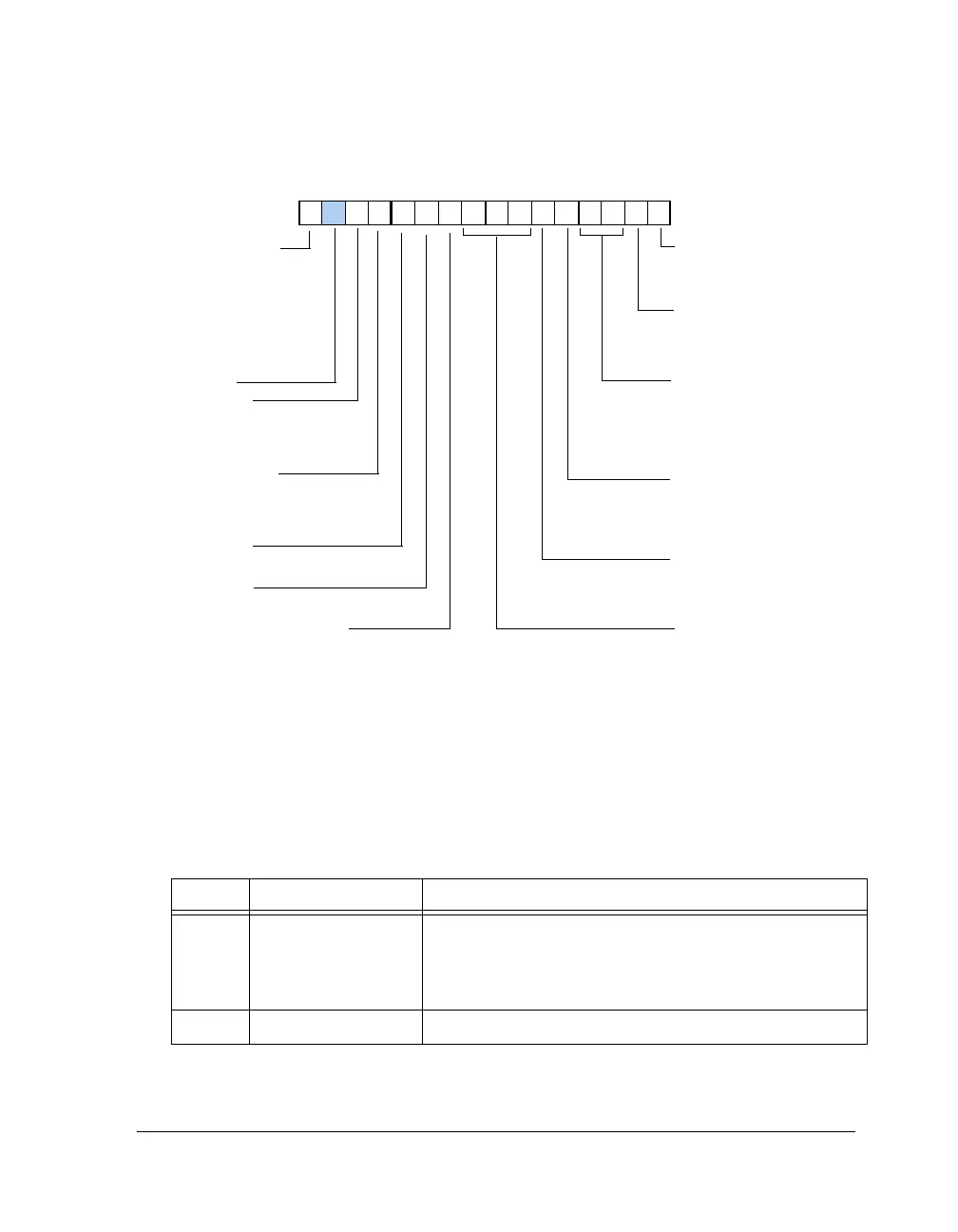
Figure A-33. DITCTL Register (Bits 15–0)
Table A-33. DITCTL Register Bit Descriptions
Bit Name Description
0 DIT_EN Transmitter Enable. Enables the transmitter and resets the
control registers to their defaults.
0 = Transmitter disabled
1 = Transmitter enabled
1 DIT_MUTE Mute. Mutes the serial data output.
DIT_EN
DIT_MUTE
DIT_VALIDL
DIT_VALIDR
Validity bit B use with channel status buffer
Validity bit A use with channel status buffer
Mute Serial Data Output
0=Not muted
1=Muted
Transmitter Enable
0=Transmitter disabled
1=Transmitter enabled
15 14 13 12 11 10 9 8 7 6 5 4 3 2 1 0
0000000000000000
Reserved
DIT_SMODE_IN
Serial Data Input Format
000=Left-justified
001=I
2
S
010–011=Reserved
100=Right-justified, 24 bits
101=Right-justified, 20 bits
110=Right-justified, 18 bits
111=Right-justified, 16 bits
DIT_FREQ
Oversampling Ratio
00=256 x Fs
01=384 x Fs
10=512 x Fs
11=786 x Fs
DIT_SCDF
Single Channel Double Fre-
quency Mode Enable
0=Disabled, 2 channel mode
1=Enabled
DIT_SCDF_LR
Select SCDF Channel
0=Left channel
1=Right channel
DIT_EXT_SYNCEN
External Sync Enable
0=Internal frame counter not
set to zero at the next LRCLK
rising edge
1=Internal frame counter is
set to zero at the next LRCLK
rising edge
DIT_STANDALONE_MODE
Standalone Mode
0=Full serial mode
1=Standalone mode
DIT_USERS
This bit is high if user bits buffer
has been written but not fully
transmitted.
DIT_BLK_STAT
Block Status (Based on Bit 9 = 1)
0 =Current word is not block start
1 =Current word is block start
 Loading...


