Signal Routing Units
4-14 ADSP-21368 SHARC Processor Hardware Reference
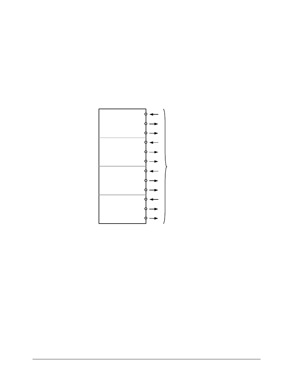
For example, from an external perspective, when a serial port (SPORT) is
completely routed off chip, it uses four pins—clock, frame sync, data
channel A, and data channel B. Because all four of these pins comprise the
interface that the serial port presents to SRU1, there are a total of 12 con-
nections as shown in Figure 4-9.
For each bidirectional line, the serial port provides three separate signals.
For example, a SPORT clock has three separate SRU connections—an
input clock to the SPORT (
SPORTx_CLK_I), an output clock from the
SPORT (
SPORTx_CLK_O), and an output enable from the SPORT
(
SPORTx_CLK_PBEN_O). Note that the input and output signal pair is never
used simultaneously. The pin enable signal dictates which of the two
SPORT lines appear at the DAI pin at any given time. By connecting all
three signals through SRU1, the standard SPORT configuration registers
behave as documented in “SPORT Serial Control Registers (SPCTLx)” on
Figure 4-9. SRU1 Connections for SPORTx
Interface
to SRU
SPORT0_DA_O
SPORT0_DA_I
SPORT0_DA_PBEN_O
SPORT0_FS_O
SPORT0_FS_I
SPORT0_FS_PBEN_O
SPORT0_CLK_O
SPORT0_CLK_I
SPORT0_CLK_PBEN_O
SPORT0_DB_O
SPORT0_DB_I
SPORT0_DB_PBEN_O
 Loading...


