ADSP-21368 SHARC Processor Hardware Reference 4-17
Digital Audio/Digital Peripheral Interfaces
another peripheral. All of the possible encodings represent sources that are
clock signals (or at least could be clock signals in some systems).
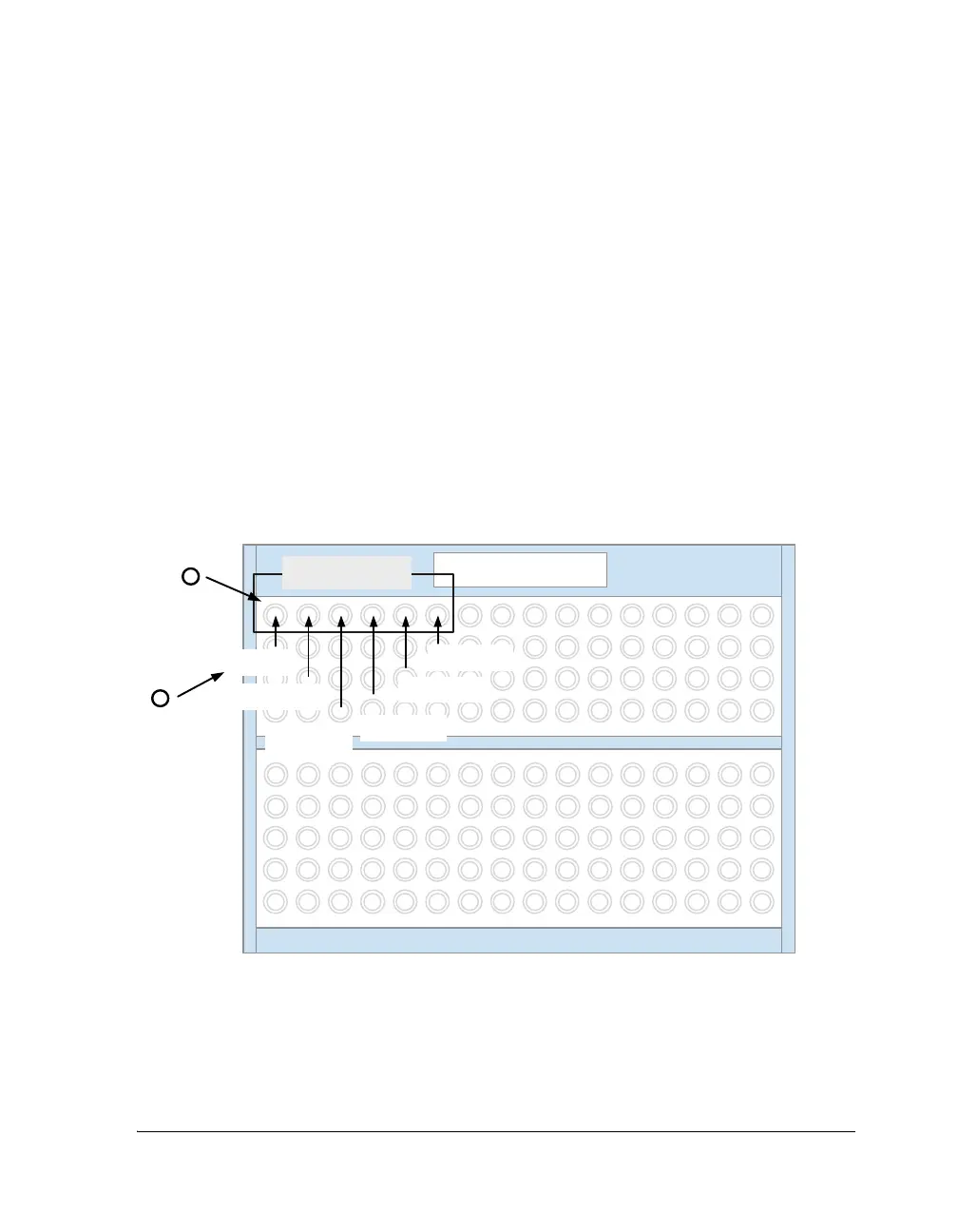
Figure 4-11 diagrams the input signals that are controlled by the DAI
group A register,
SRU_CLK0. All bit fields in the SRU1 configuration regis-
ters correspond to inputs. The value written to the bit field specifies the
signal source. This value is also an output from some other component
within the SRU.
Note that the lower portion of the patch bay in Figure 4-11 is shown with
a large number of ports to reinforce the point that one output can be con-
nected to many inputs. The same encoding can be written to any number
of bit fields in the same group. It is not possible to run out of patch points
for an output signal.
Figure 4-11. Patching to the Group A Register SRU_CLK0
2
SRU: GROUP A
SRU_CLK0
SPORT5_CLK_I
(11001)
SPORT4_CLK_I
(11000)
SPORT3_CLK_I
(10111)
SPORT0_CLK_I
(10100)
SPORT1_CLK_I
(10101)
SPORT2_CLK_I
(10110)
4:09:514:1019:1524:2029:25
1
 Loading...


