PWM Implementation
8-14 ADSP-21368 SHARC Processor Hardware Reference
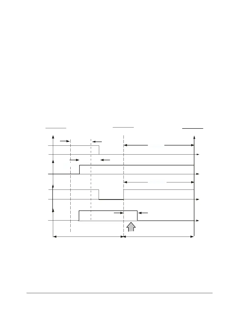
Figure 8-4 illustrates two examples of such transitions. In Figure 8-4 (A),
when transitioning from normal modulation to full on at the half cycle
boundary in double-update mode, no special action is needed. However,
in Figure 8-4 (B), when transitioning into full off at the same boundary,
an additional emergency dead time is necessary. This inserted dead time is
a little different to the normal dead time as it is impossible to move one of
the switching events back in time because this would move the event into
the previous modulation cycle. Therefore, the entire emergency dead time
is inserted by delaying the turn on of the appropriate signal by the full
amount.
Figure 8-4. Full On to Full Off Transition
............................................
PWMPER
OD PWMPERIOD
PWMPERIOD
1
2
+0
_
+
pwm_ah
pwm_al
pwm_ah
pwm_al
............................................
FULL OFF
FULL ON
2xPWMDT
PWMCHA
1
DeadTime Inserted
(A)
(B)
2xPWMDT
PWMPERIOD
1
2
PWMPERIOD
2
2
 Loading...


