I/O Processor Registers
A-6 ADSP-21368 SHARC Processor Hardware Reference
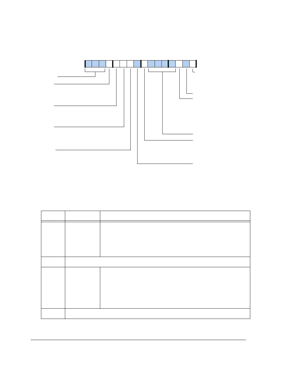
Figure A-2. SYSCTL Register (Bits 15–0)
Table A-1. SYSCTL Register Bit Descriptions
Bit Name Description
0 SRST Software Reset. When set, this bit resets the processor and the proces-
sor responds to the non-maskable RSTI interrupt and clears (=0)
SRST. Permits core writes.
0 = No software reset
1 = Software reset
1Reserved
2 IIVT Internal Interrupt Vector Table. This bit forces placement of the
interrupt vector table at address 0x0008 0000 regardless of booting
mode or allows placement of the interrupt vector table as selected by
the booting mode. Permits core writes.
0 = Interrupt vector table not in internal RAM
1 = Interrupt vector table in internal RAM
6–3 Reserved
15 14 13 12 11 10 9 8 7 6 5 4 3 2 1 0
0000000000000000
SRST
IMDW2
IMDW3
Reserved
Internal Memory Block 3 Data Width
1=Data bus width is 48 bits
0=Data bus is 32 bits
Software Reset
1=Software reset
0=No software reset
Internal Memory Block 2 Data Width
1=Data bus width is 48 bits
0=Data bus is 32 bits
Reserved
Reserved
IIVT
Internal Interrupt Vector
Table
1=Interrupt vector table in
internal RAM
0=Interrupt vector table not
in internal RAM
Reserved
RPBR
Rotating Priority Bus
Arbitration
1=Rotating priority
0=Fixed priority
SYSCTL (0x30024)
IMDW0
IMDW1
Internal Memory Block 1 Data Width
1=Data bus width is 48 bits
0=Data bus is 32 bits
Internal Memory Block 0 Data Width
1=Data bus width is 48 bits
0=Data bus is 32 bits
 Loading...


