Serial Port Registers
A-38 ADSP-21368 SHARC Processor Hardware Reference
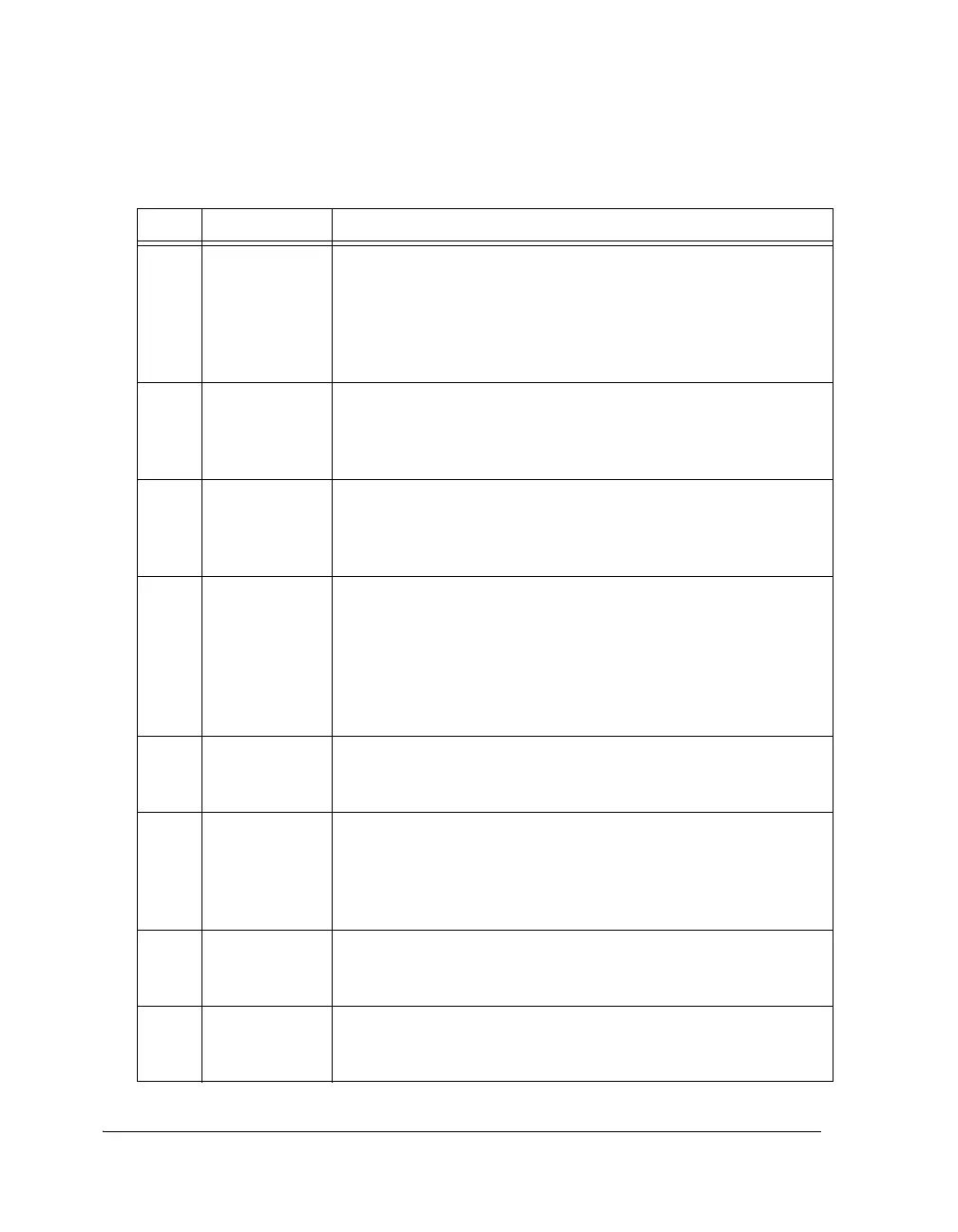
12 CKRE Clock Rising Edge Select. Determines clock signal to sample data and
the frame sync selection.
0 = Falling edge
1 = Rising edge
CKRE is reserved when the SPORT is in I
2
S and left-justified sample
pair modes.
13 FSR Frame Sync Required Select. Selects whether the serial port requires
(if set, = 1) or does not require a transfer frame sync (if cleared, = 0).
FSR is reserved when the SPORT is in packed I
2
S, I
2
S, left-justified
sample pair, and multichannel modes. See Table A-7 on page A-30.
14 IFS
(IMFS)
Internal Frame Sync Select. Selects whether the serial port uses an
internally-generated frame sync (if set, = 1) or uses an external frame
sync (if cleared, = 0). This bit is reserved when the SPORT is in I
2
S
mode, left-justified sample pair mode. See Table A-7 on page A-30.
15 DIFS Data Independent Frame Sync Select.
1 = Serial port uses a data-independent frame sync (sync at selected
interval)
0 = Serial port uses a data-dependent frame sync (sync when TX FIFO
is not empty or when RX FIFO is not full). This bit is reserved when
the SPORT is in packed I
2
S and multichannel modes. See Table A-7
on page A-30.
16 LFS, FRFS,
LMFS
Active Low Frame Sync Select. Depending on the OPMODE, selects
an active high or low, left or right channel frame sync. See Table A-7
on page A-30.
17 LAFS Late Transmit Frame Sync Select.
0 = Early frame sync (FS before first bit).
1 = Late frame sync (FS during first bit)
This bit is reserved when the SPORT is in packed I
2
S and multichan-
nel modes. See Table A-7 on page A-30.
18 SDEN_A Enable Channel A Serial Port DMA.
0 = Disable serial port channel A DMA
1 = Enable serial port channel A DMA
19 SCHEN_A Enable Channel A Serial Port DMA Chaining.
0 = Disable serial port channel A DMA chaining
1 = Enable serial port channel A DMA chaining
Table A-8. SPCTLx Register Bit Descriptions (Cont’d)
Bit Name Description
 Loading...


