R01UH0823EJ0100 Rev.1.00 Page 1142 of 1823
Jul 31, 2019
RX23W Group 35. I
2
C-bus Interface (RIICa)
35.2.14 I
2
C-bus Bit Rate High-Level Register (ICBRH)
ICBRH is a 5-bit register to set the high-level period of SCL clock. ICBRH is valid in master mode. If the RIIC is used
only in slave mode, this register need not to set the high-level period.
ICBRH counts the high-level period with the internal reference clock (IICφ) specified by the ICMR1.CKS[2:0] bits.
If the digital noise filter is enabled (the ICFER.NFE bit is 1), set the ICBRH register to a value at least one greater than
the number of stages in the noise filter. Regarding the number of stages in the noise filter, see the description of the
ICMR3.NF[1:0] bits.
The I
2
C transfer rate and the SCL clock duty are calculated using the following expression.
Transfer rate = 1 / {[(ICBRH + 1) + (ICBRL + 1)] / IICφ
*
1
+ SCL0 line rising time [tr] + SCL0 line falling time [tf]}
Duty cycle = {SCL0 line rising time [tr]
*
2
+ (ICBRH + 1) / IICφ} / {SCL0 line falling time [tf]*
2
+ (ICBRL + 1) / IICφ}
Note 1. IICφ = PCLK × Division ratio
Note 2. The SCL0 line rising time [tr] and SCL0 line falling time [tf] depend on the total bus line capacitance [Cb] and the
pull-up resistor [Rp]. For details, see the I
2
C-bus specification from NXP Semiconductors.
Table 35.5 lists examples of ICBRH/ICBRL settings.
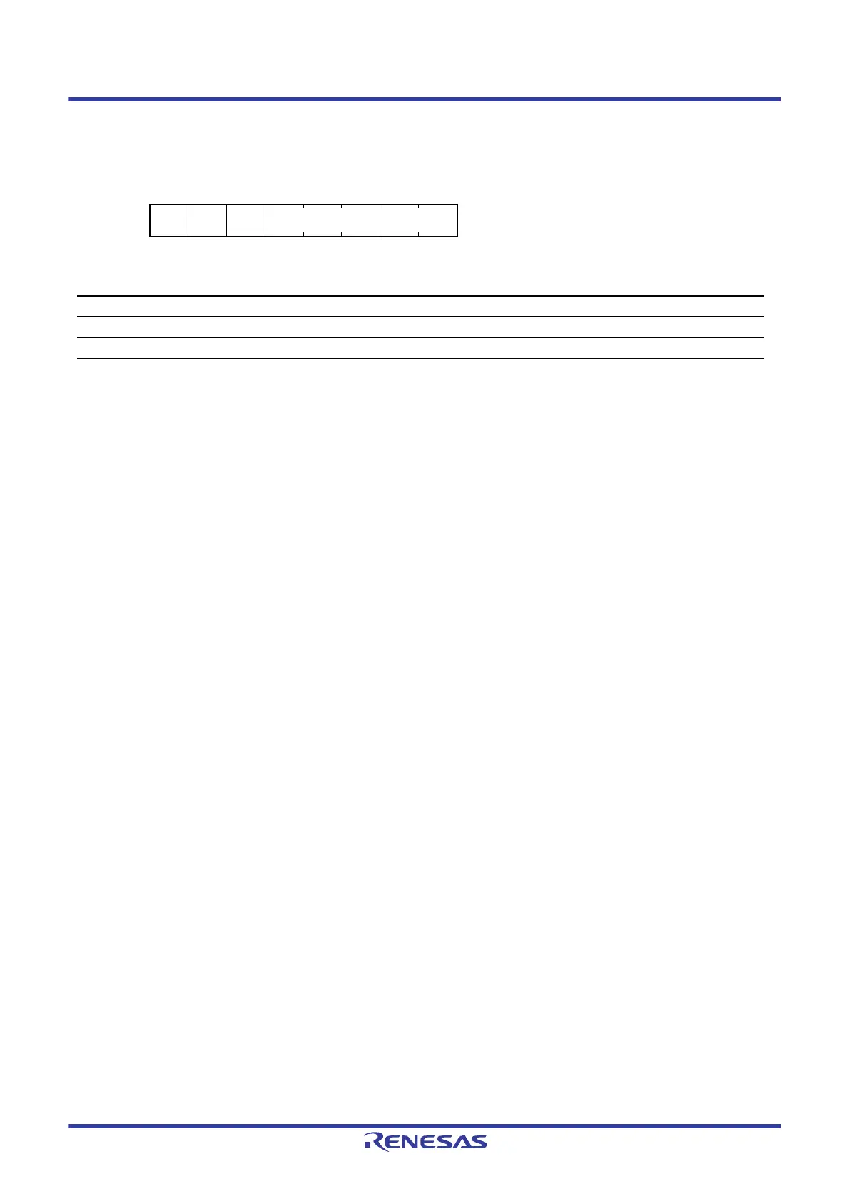
Address(es): RIIC0.ICBRH 0008 8311h
b7 b6 b5 b4 b3 b2 b1 b0
——— BRH[4:0]
Value after reset:
11111111
Bit Symbol Bit Name Description R/W
b4 to b0 BRH[4:0] Bit Rate High-Level Period High-level period of SCL clock R/W
b7 to b5 — Reserved These bits are read as 1. The write value should be 1. R/W

 Loading...


