R01UH0823EJ0100 Rev.1.00 Page 1777 of 1823
Jul 31, 2019
RX23W Group 51. Electrical Characteristics
51.3.4 Control Signal Timing
Note: 200 ns minimum in software standby mode.
Note 1. t
Pcyc
indicates the cycle of PCLKB.
Note 2. t
NMICK
indicates the cycle of the NMI digital filter sampling clock.
Note 3. t
IRQCK
indicates the cycle of the IRQi digital filter sampling clock (i = 0 to 7).
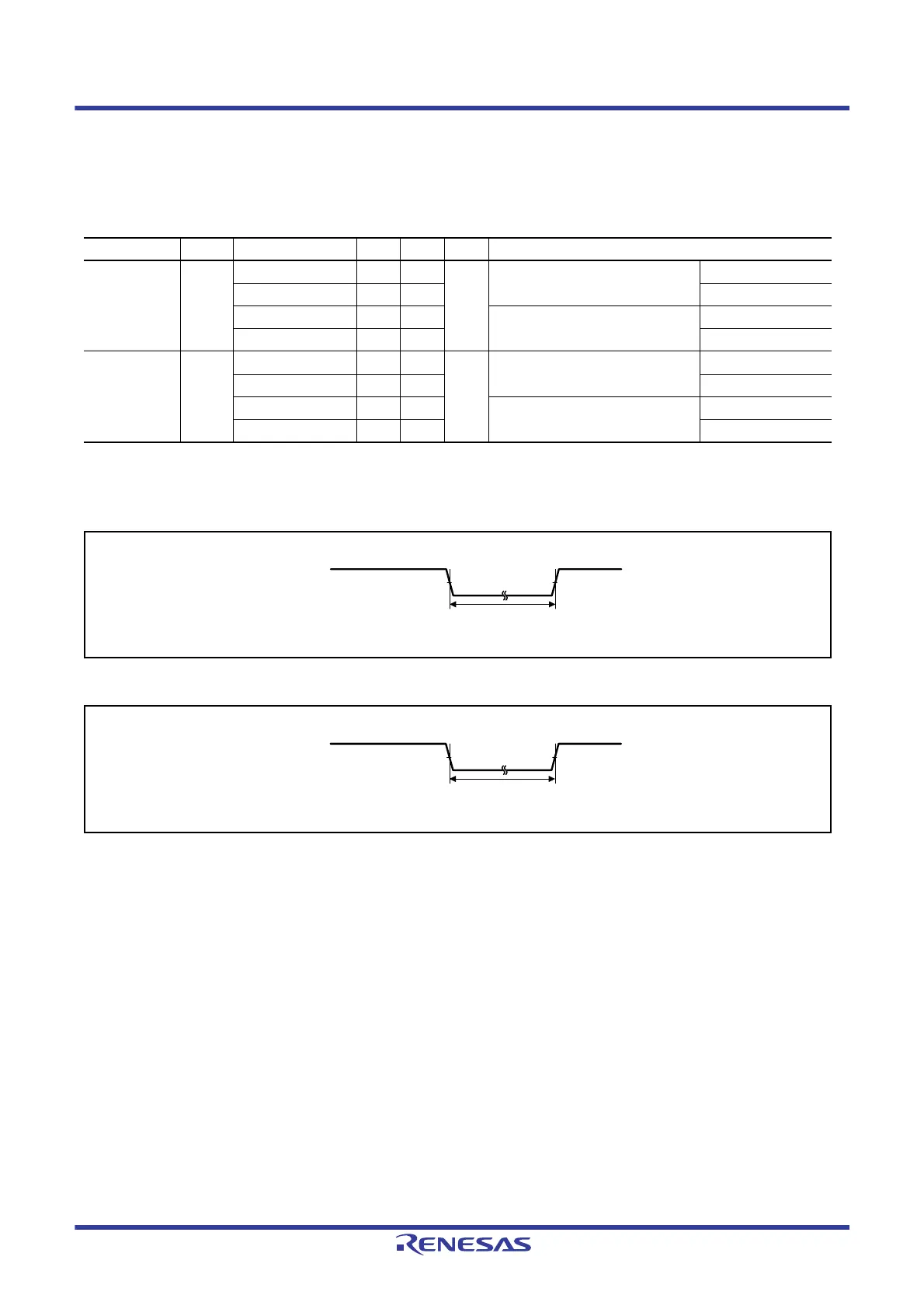
Figure 51.32 NMI Interrupt Input Timing
Figure 51.33 IRQ Interrupt Input Timing
Table 51.31 Control Signal Timing
Conditions: 1.8 V ≤ VCC = VCC_USB = AVCC0 = VCC_RF = AVCC_RF ≤ 3.6 V, VSS = AVSS0 = VSS_USB = VSS_RF = 0 V,
T
a
= –40 to +85°C
Item Symbol Min. Typ. Max. Unit Test Conditions
NMI pulse width t
NMIW
200 — — ns NMI digital filter is disabled
(NMIFLTE.NFLTEN = 0)
t
Pcyc
× 2 ≤ 200 ns
t
Pcyc
× 2*
1
—— t
Pcyc
× 2 > 200 ns
200 — — NMI digital filter is enabled
(NMIFLTE.NFLTEN = 1)
t
NMICK
× 3 ≤ 200 ns
t
NMICK
× 3.5*
2
—— t
NMICK
× 3 > 200 ns
IRQ pulse width t
IRQW
200 — — ns IRQ digital filter is disabled
(IRQFLTE0.FLTENi = 0)
t
Pcyc
× 2 ≤ 200 ns
t
Pcyc
× 2*
1
—— t
Pcyc
× 2 > 200 ns
200 — — IRQ digital filter is enabled
(IRQFLTE0.FLTENi = 1)
t
IRQCK
× 3 ≤ 200 ns
t
IRQCK
× 3.5*
3
—— t
IRQCK
× 3 > 200 ns
 Loading...


