R01UH0823EJ0100 Rev.1.00 Page 1364 of 1823
Jul 31, 2019
RX23W Group 38. Serial Peripheral Interface (RSPIa)
38.3.3.5 Multi-Master/Multi-Slave (with This MCU Acting as Master)
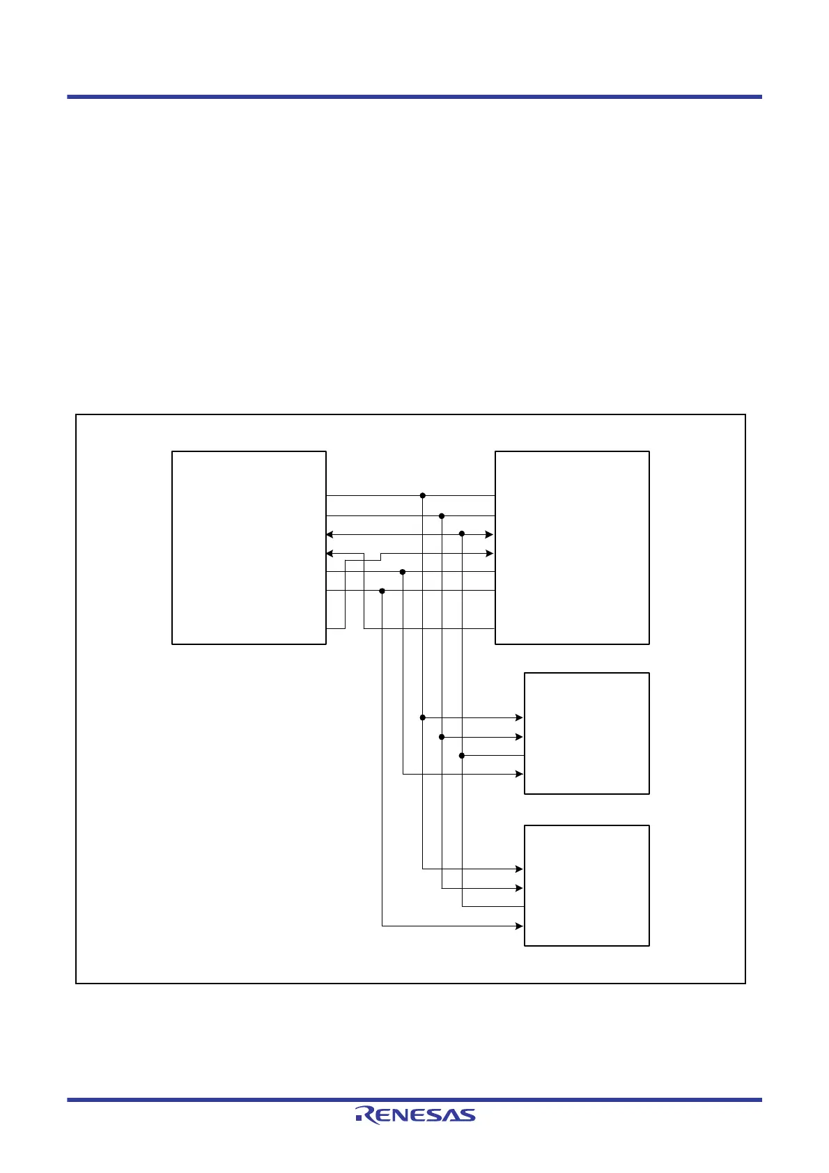
Figure 38.10 shows a multi-master/multi-slave RSPI system configuration example when this MCU is used as a master.
In the example of
Figure 38.10, the RSPI system is comprised of two MCUs (master X and master Y) and two SPI
slaves (SPI slave 1 and SPI slave 2).
The RSPCKA and MOSIA outputs of the MCUs (master X and master Y) are connected to the RSPCK and MOSI inputs
of SPI slaves 1 and 2. The MISO outputs of SPI slaves 1 and 2 are connected to the MISOA inputs of the MCUs (master
X and master Y). Any generic port Y output from this MCU (master X) is connected to the SSLA0 input of this MCU
(master Y). Any generic port X output of this MCU (master Y) is connected to the SSLA0 input of this MCU (master X).
The SSLA1 and SSLA3 outputs of the MCUs (master X and master Y) are connected to the SSL inputs of the SPI slaves
1 and 2.
This MCU drives RSPCKA, MOSIA, SSLA1, and SSLA3 when the SSLA0 input level is high. When the SSLA0 input
level is low, this MCU detects a mode fault error, sets RSPCKA, MOSIA, SSLA1, and SSLA3 to Hi-Z, and releases the
RSPI bus right to the other master. Of the SPI slaves 1 and 2, the slave that receives low-level input into the SSL input
drives MISO.
Figure 38.10 Multi-Master/Multi-Slave Configuration Example (This MCU = Master)
RSPCK
MOSI
MISO
SSL0
SSL1
SSL2
SSL3
Port Y
RSPCK
MOSI
MISO
SSL0
SSL1
SSL2
SSL3
SPCK
MOSI
MISO
SPCK
MOSI
MISO
SPI slave 1
This MCU (master X) This MCU (master Y)
Port X
SPI slave 2
SSL
SSL
RSPCKA
MOSIA
MISOA
SSLA0
SSLA1
SSLA3
RSPCKA
MOSIA
MISOA
SSLA0
SSLA1
SSLA3

 Loading...


