R01UH0823EJ0100 Rev.1.00 Page 1551 of 1823
Jul 31, 2019
RX23W Group 44. 12-Bit A/D Converter (S12ADE)
44.2.12 A/D Conversion Start Trigger Select Register (ADSTRGR)
ADSTRGR selects the A/D conversion start trigger.
TRSB[5:0] Bits (A/D Conversion Start Trigger Select for Group B)
The TRSB[5:0] bits select the trigger to start scanning of the analog input selected in group B. The TRSB[5:0] bits
require to be set only in group scan mode and are not used in any other scan mode. For the scan conversion start trigger
for group B, setting a software trigger or an asynchronous trigger is prohibited. Therefore, the TRSB[5:0] bits should be
set to the value other than 000000b and the ADCSR.TRGE bit should be set to 1 in group scan mode.
When group A is given priority in group scan mode, setting the ADGSPCR.GBRP bit to 1 allows group B to
continuously operate in single scan mode. When setting the ADGSPCR.GBRP bit to 1, set the TRSB[5:0] bits to 3Fh.
Note that the issuance period of trigger for A/D conversion must be more than or equal to the actual scan conversion time
(t
SCAN
). If the issuance period is less than t
SCAN
, A/D conversion by the trigger may have no effect.
When the trigger from the module operated in 54 MHz (MTU) is selected as an A/D conversion start trigger, a delay of
the period for synchronization processing occurs. See
section 44.3.6, Analog Input Sampling Time and Scan
Conversion Time
for details.
Table 44.6 lists the A/D conversion startup sources selected by the TRSB[5:0] bits.
TRSA[5:0] Bits (A/D Conversion Start Trigger Select)
The TRSA[5:0] bits select the trigger to start A/D conversion in single scan mode and continuous scan mode. In group
scan mode, the trigger to start scanning of the analog input selected in group A is selected. When scanning is executed in
group scan mode or double trigger mode, software trigger and asynchronous trigger cannot be used.
When using the A/D conversion startup source of a synchronous trigger, set the ADCSR.TRGE bit to 1 and set the
ADCSR.EXTRG bit to 0.
When using the asynchronous trigger, set the ADCSR.TRGE bit to 1 and set the ADCSR.EXTRG bit to 1.
Software trigger (ADCSR.ADST) is enabled regardless of the settings of the ADCSR.TRGE bit, the
ADCSR.EXTRG bit, and the TRSA[5:0] bits.
Note that the issuance period of trigger for A/D conversion must be more than or equal to the actual scan conversion time
(t
SCAN
). If the issuance period is less than t
SCAN
, A/D conversion by a trigger may have no effect. When the trigger from
the module operated in 54 MHz (MTU) is selected as an A/D conversion start trigger, a delay of the period for
synchronization processing occurs. See
section 44.3.6, Analog Input Sampling Time and Scan Conversion Time
for details.
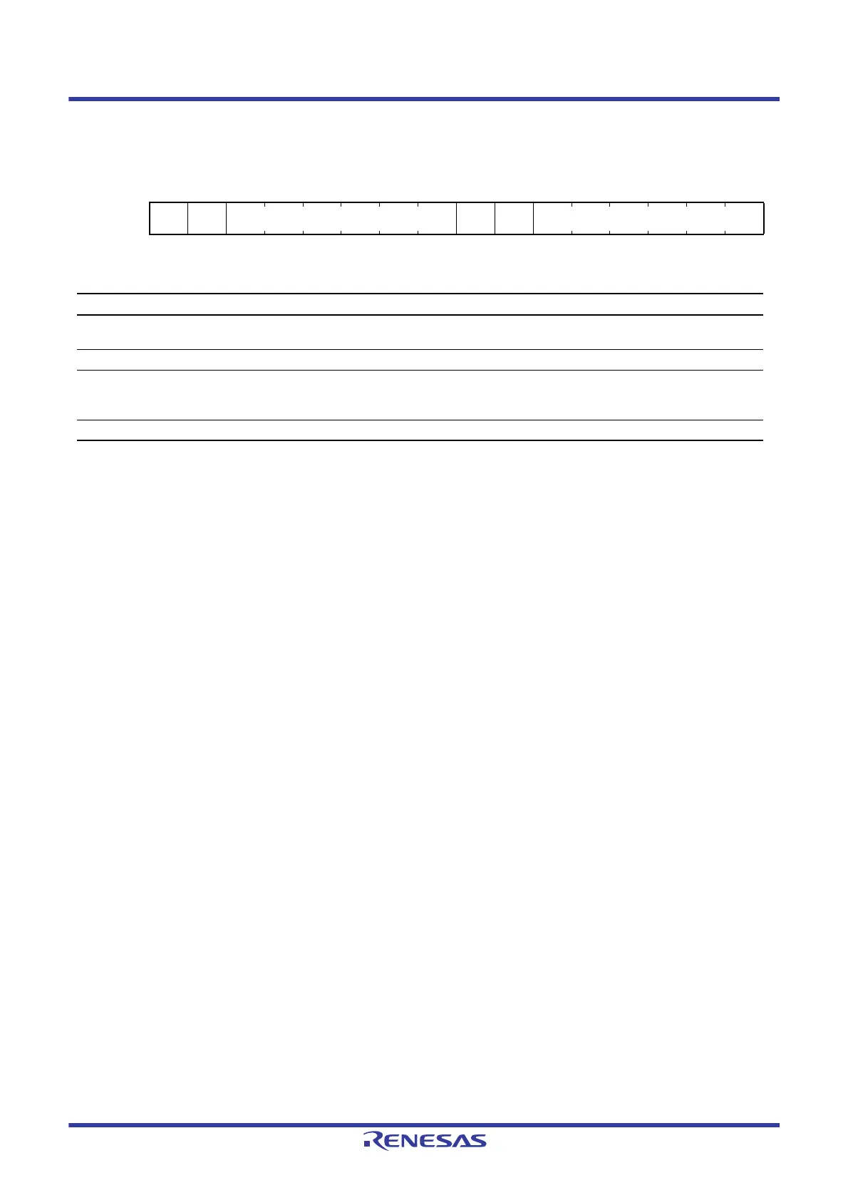
Address(es): S12AD.ADSTRGR 0008 9010h
b15 b14 b13 b12 b11 b10 b9 b8 b7 b6 b5 b4 b3 b2 b1 b0
— — TRSA[5:0] — — TRSB[5:0]
Value after reset:
0000000000000000
Bit Symbol Bit Name Description R/W
b5 to b0 TRSB[5:0] A/D Conversion Start Trigger Select
for Group B
Select the A/D conversion start trigger for group B in
group scan mode.
R/W
b7, b6 — Reserved These bits are read as 0. The write value should be 0. R/W
b13 to b8 TRSA[5:0] A/D Conversion Start Trigger Select Select the A/D conversion start trigger in single scan
mode and continuous mode. In group scan mode, the A/D
conversion start trigger for group A is selected.
R/W
b15, b14 — Reserved These bits are read as 0. The write value should be 0. R/W

 Loading...


