R01UH0823EJ0100 Rev.1.00 Page 1145 of 1823
Jul 31, 2019
RX23W Group 35. I
2
C-bus Interface (RIICa)
35.3 Operation
35.3.1 Communication Data Format
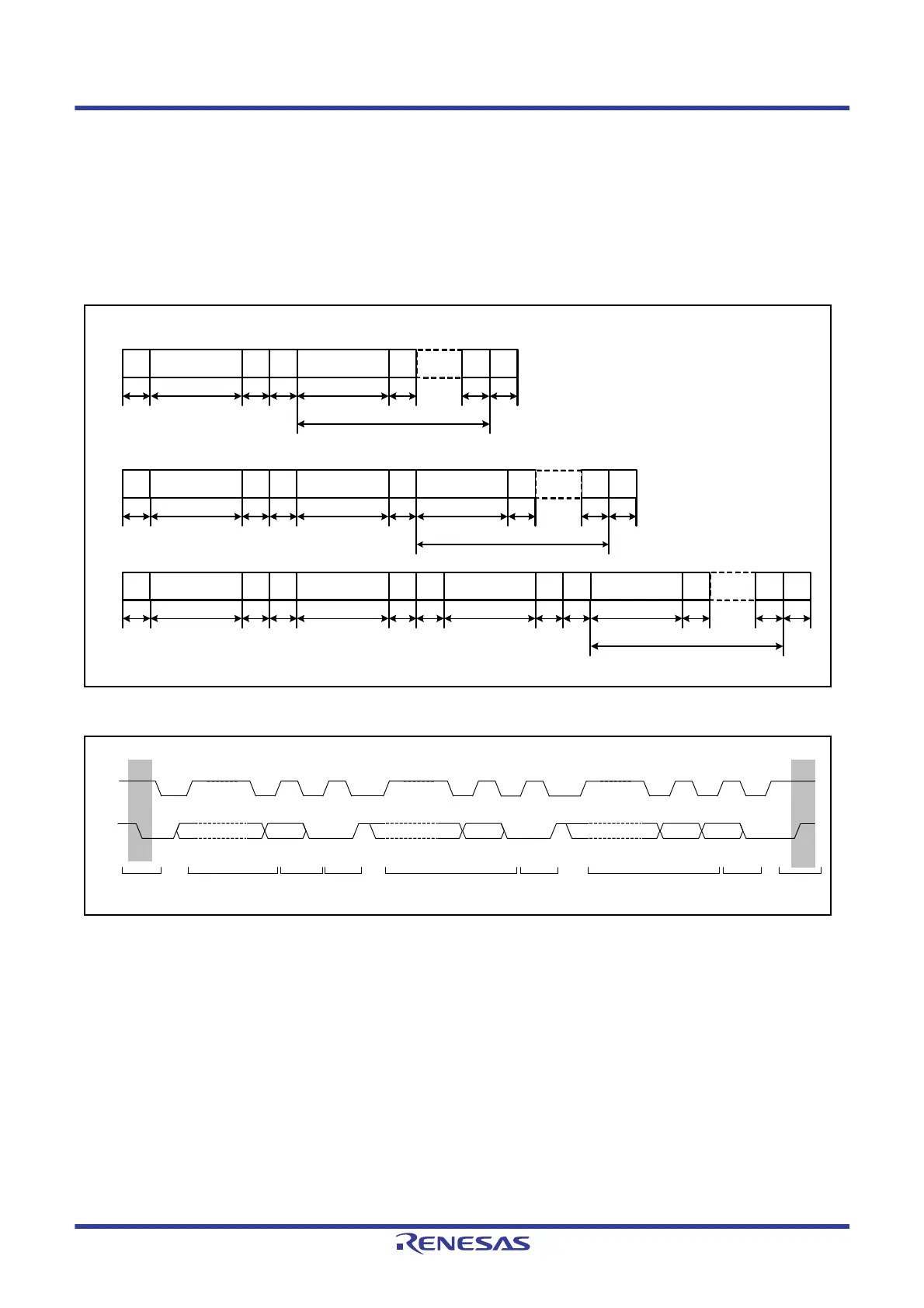
The I
2
C-bus format consists of 8-bit data and 1-bit acknowledge. The first byte following a start condition or restart
condition is an address byte used to specify a slave device with which the master device communicates. The specified
slave is valid until a new slave is specified or a stop condition is issued.
Figure 35.3 shows the I
2
C-bus format, and Figure 35.4 shows the I
2
C-bus timing.
Figure 35.3 I
2
C-bus Format
Figure 35.4 I
2
C-bus Timing (SLA = 7 Bits)
S: Start condition. The master device drives the SDA0 line low from high level while the SCL0 line is at a high level.
SLA: Slave address, by which the master device selects a slave device.
R/W#: Indicates the direction of data transfer: from the slave device to the master device when R/W is 1, or from the master device to
the slave device when R/W is 0.
A: Acknowledge. The receive device drives the SDA0 line low. (In master transmit mode, the slave device returns acknowledge.
In master receive mode, the master device returns acknowledge.)
A#: Not Acknowledge. The receive device drives the SDA0 line high.
Sr: Restart condition. The master device drives the SDA0 line low from the high level after the setup time has elapsed with the
SCL0 line at the high level.
DATA: Transmitted or received data
P: Stop condition. The master device drives the SDA0 line high from low level while the SCL0 line is at a high level.
[7-bit address format]
S R/W# A A A/A# P
S
SLA (7 bits)
W# A A A/A# PSLA (8 bits)11110b+SLA(2 bits)
DATA (8 bits)
A
S W# A A A/A# PSLA (8 bits)11110b+SLA(2 bits) ASr 11110b+SLA(2 bits) R
DATA (8 bits)
1 7 11 1 118
ADATA (8 bits)
1 7 11 1 118
1118
18
1 7 11 181 17 1
[10-bit address format]
n (n = 1 or more)
n (n = 1 or more)
n (n = 1 or more)
n: Number of transmit DATA bytes
1 to 7 8 9 1 to 7 8 9 1 to 7 8 9
S
SLA
R/W# A Data A Data A P
 Loading...


