R01UH0823EJ0100 Rev.1.00 Page 739 of 1823
Jul 31, 2019
RX23W Group 26. 8-Bit Timer (TMR)
26.3 Operation
26.3.1 Pulse Output
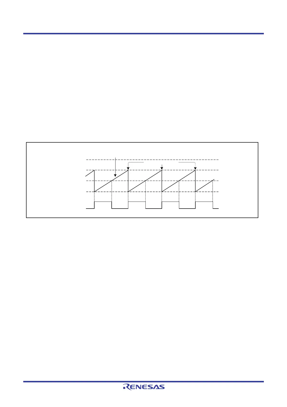
Figure 26.3 shows an example of the 8-bit timer being used to generate a pulse output with a desired duty cycle.
1. Set the TCR.CCLR[1:0] bits to 01b (cleared by compare match A) so that TCNT is cleared at a compare match of
TCORA.
2. Set the TCSR.OSA[1:0] bits to 10b (high is output) and TCSR.OSB[1:0] bits to 01b (low is output), causing the
output to change to high at a compare match of TCORA and to low at a compare match of TCORB.
With these settings, the 8-bit timer provides pulses output at a cycle determined by TCORA with a pulse width
determined by TCORB. No software intervention is required.
The timer output pin is low after the TCSR.OSA[1:0] or TCSR.OSB[1:0] bits are set until the first compare match occurs
after a reset.
Figure 26.3 Example of Pulse Output (n = 0 to 2)
TCNT
FFh
Counter clear
TCORA
TCORB
00h
TMOn

 Loading...


