R01UH0823EJ0100 Rev.1.00 Page 1067 of 1823
Jul 31, 2019
RX23W Group 33. Serial Communications Interface (SCIg, SCIh)
33.7.5 Operation in Master Transmission (Simple I
2
C Mode)
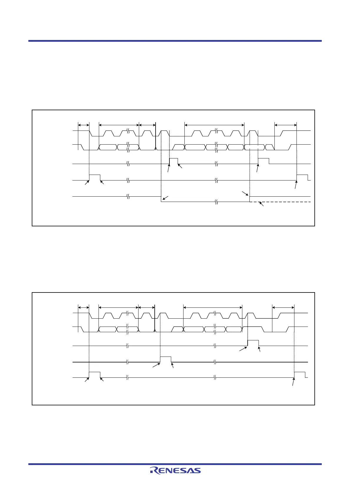
Figure 33.52 and Figure 33.53 show examples of operations in master transmission and Figure 33.54 is a flowchart
showing the procedure for data transmission. Refer to
Table 33.33 for more information on the STI interrupt.
When 10-bit slave addresses are in use, steps [3] and [4] in
Figure 33.54 are repeated twice.
In simple I
2
C mode, the transmit data empty interrupt (TXI) is generated when communication of one frame is
completed, unlike the TXI interrupt request generation timing during clock synchronous transmission.
Figure 33.52 Example 1 of Operations for Master Transmission in Simple I
2
C-bus Mode
(with 7-Bit Slave Addresses, Transmission Interrupts, and Reception Interrupts in Use)
When the SIMR2.IICINTM bit is set to 0 (use ACK/NACK interrupts) during master transmission, the DTC or DMAC is
activated by the ACK interrupt as the trigger and necessary number of data bytes are transmitted. When the NACK is
received, error processing, such as transmission stop and retransmission, is performed by the NACK interrupt as the
trigger.
Figure 33.53 Example 2 of Operations for Master Transmission in Simple I
2
C-bus Mode
(with 7-Bit Slave Addresses, ACK Interrupts, and NACK Interrupts in Use)
TXI interrupt flag
(IRn in the ICU*
1
)
SSDAn
SSCLn
Generation of STI interrupt
STI interrupt flag
(IRn in the ICU*
1
)
Acceptance of request
Generation of TXI interrupt request
Acceptance of TXI interrupt request
Generation of TXI interrupt request
Generation of request
D7 D6 D1 D0
ACK
D7 D6 D1 D0
Slave address (7 bits)
W#
Transmitted dataStart condition Stop condition
SISR.IICACKR flag
Reception of ACK
Reception of ACK
Reception of NACK
ACK/NACK
Note1. Refer to section 15, Interrupt Controller (ICUb) for details on the corresponding interrupt vector number.
TXI interrupt flag
(IRn in the ICU*
1
)
SSDAn
SSCLn
RXI interrupt flag
(IRn in the ICU*
1
)
Generation of RXI interrupt request
D7 D6 D1 D0
ACK
D7 D6 D1 D0 NACK
Slave address (7 bits)
W#
Transmitted dataStart condition Stop condition
Generation of STI interrupt request
STI interrupt flag
(IRn in the ICU*
1
)
Acceptance of STI interrupt request
Generation of STI interrupt request
Acceptance or RXI interrupt request
Generation of TXI interrupt request
Acceptance of TXI
interrupt request
Note1. Refer to section 15, Interrupt Controller (ICUb) for details on the corresponding interrupt vector number.

 Loading...


