R01UH0823EJ0100 Rev.1.00 Page 206 of 1823
Jul 31, 2019
RX23W Group 9. Clock Generation Circuit
9.9.4 Notes on Resonator Connection Pins
When the main clock is not used, the EXTAL and XTAL pins can be used as general ports P36 and P37. When using
these pins as general ports, be sure to stop the main clock (MOSCCR.MOSTP = 1). However, do not use the EXTAL and
XTAL pins as general ports P36 and P37 in a system that uses the main clock.
When the main clock is used, do not set P36 and P37 to output.
9.9.5 Notes on Sub-Clock
The sub-clock can be used as the system clock, as the count source for the realtime clock, or as both. Take note of the
following limitations and points for caution regarding the settings, including when the sub-clock is not in use.
With regard to making the sub-clock oscillator run or stop, setting either the sub-clock oscillator stop bit in the
sub-clock oscillator control register (SOSCCR.SOSTP) or the sub-clock oscillator control bit in RTC control
register 3 (RCR3.RTCEN) will make the oscillator run.
To use the sub-clock as the system clock and as the count source of the realtime clock simultaneously, perform
initial settings according to the flowchart example shown in
Figure 9.14. After that, perform the clock setting
procedure shown in
section 28.3.2, Clock and Count Mode Setting Procedure.
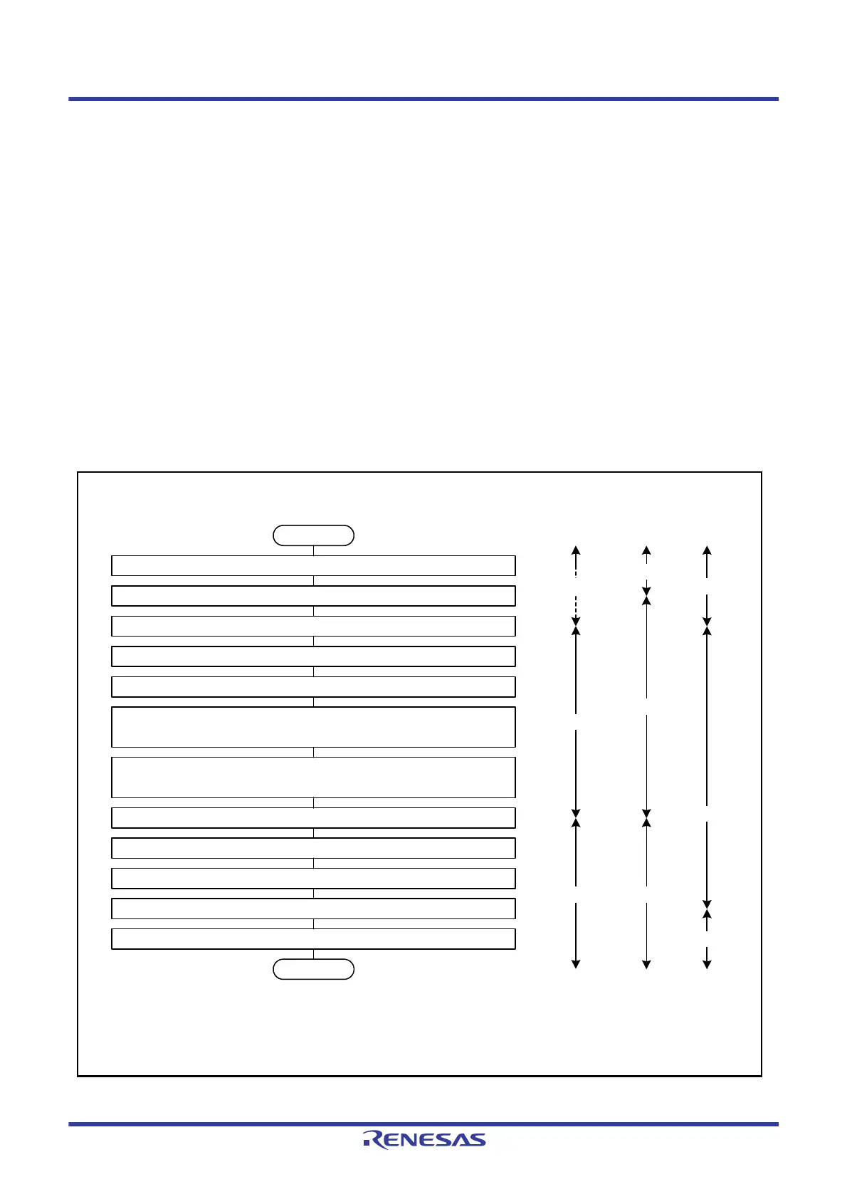
Figure 9.14 Example of Initialization Flowchart When Sub-Clock is Used as Count Source of Realtime Clock
Start
Set the SOSCCR.SOSTP bit to 1 (sub-clock oscillator is stopped).
Read the SOSCCR.SOSTP bit and confirm that it is 1.
Set the RCR3.RTCEN bit to 0 (sub-clock oscillator is stopped).
Read the RCR3.RTCEN bit and confirm that it is 0.
*1
Wait for at least five cycles (about 153 µs) of the sub-clock to elapse.
Set bit 3 to bit 1 in the RCR3 register (or the RCR3.RTCDV[2:0] bits) to
001b or 110b.
Read bit 3 to bit 1 in the RCR3 register (or the RCR3.RTCDV[2:0] bits) and
confirm that they have been rewritten.
Set the SOSCCR.SOSTP bit to 0 (sub-clock oscillator is operating).
Read the SOSCCR.SOSTP bit and confirm that it is 0.
Wait for the oscillation stabilization time of the sub-clock to elapse by software.
Set the RCR3.RTCEN bit to 1 (sub-clock oscillator is operating).
Read the RCR3.RTCEN bit and confirm that it is 1.
End
Sub-clock
oscillation state
Stopped
SOSCCR.
SOSTP
RCR3.
RTCEN
0
Undefined
0
1
0
Note 1. The values of bit 7 to bit 1 are undefined. Confirm only the value of the RCR3.RTCEN bit.
Oscillating
Oscillating
1

 Loading...


