R01UH0823EJ0100 Rev.1.00 Page 1522 of 1823
Jul 31, 2019
RX23W Group 43. Capacitive Touch Sensing Unit (CTSU)
43.3.2.5 Mutual Capacitance Full Scan Mode Operation
In mutual capacitance full scan mode, measurement is performed during the high-level period of the sensor drive pulse
on the receive channel by applying the edge to the target transmit channel to be measured. A single measurement target is
measured twice, at the rising and falling edges. The difference between the data of these two measurements is used to
determine whether or not the electrode is touched, thus achieving higher touch sensitivity.
Electrostatic capacitance is measured sequentially on channels set to transmission or reception specified by the
CTSUCHTRCn and CTSUCHTRC4 registers (n = 0 to 3), and measurement targets specified by the CTSUCHACn and
CTSUCHAC4 registers (n = 0 to 3). Electrostatic capacitance is measured by combining signals from the measurement
target pins that are allocated to transmission or reception.
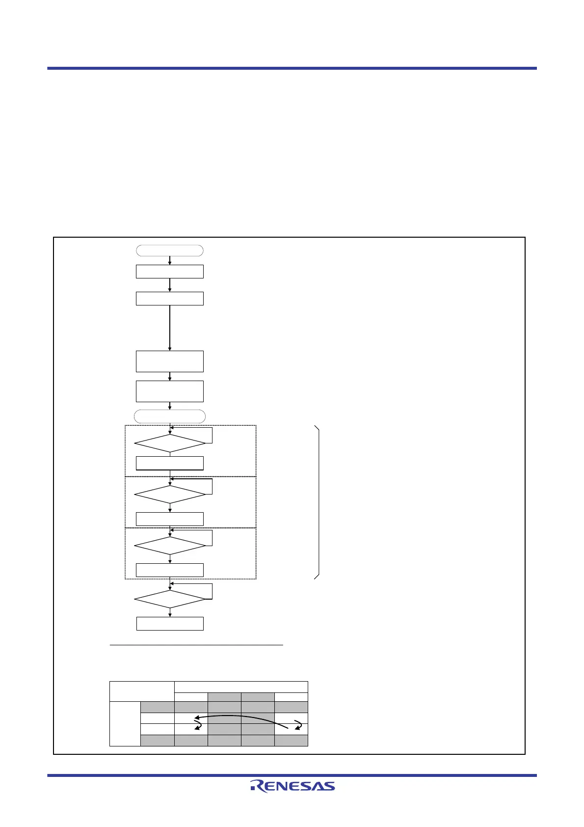
Figure 43.16 shows the software flowchart and an operation
example, and
Figure 43.17 shows the timing chart.
Figure 43.16 Software Flowchart and Operation Example of Mutual Capacitance Full Scan Mode
Set interrupt operation
(DTC/ICU)
Set CTSU registers
Set CTSU control
(measurement starts)
using CTSUCR0 register
CTSU operation starts
Power supply stabilization
time has elapsed after
CTSUPON = 1
• CTSUWR interrupt operation setting
Transfer from the RAM to the CTSUSSC, CTSUSO0, and CTSUSO1 registers
• CTSURD interrupt operation setting
Transfer the CTSUSC and CTSURC counters to the RAM
Initial setting
CTSUFN generated?
No
Touch determination
processing
Wait for the measurement end interrupt
CTSURD generated?
No
CTSUWR interrupt
generated?
No
Read the first
measurement result
Set the measurement
channel
Transferred by the DTC
when the DTC is set
Transferred by the DTC
when the DTC is set
CTSUSSC register
CTSUSO0 register
CTSUSO1 register
CTSUSC counter
CTSURC counter
CTSURD
generated?
No
Read the second
measurement result
CTSUSC counter
CTSURC counter
Transferred by the DTC
when the DTC is set
Repeat for the number of
the measurement channels
Channel measurement sequence in mutual capacitance full scan mode
Channel 3
Receive Channels
Channel 2 Channel 1 Channel 0
Channel 4
Channel 5
Channel 6
Channel 7
Transmit
channels
When a software trigger is used, the CTSUCR0.CTSUSTRT bit is set to 0 when CTSU operation is finished.
(1)
(2)
(3)
(4)
CTSUCR0.CTSUSTRT bit: Set this bit to 1
CTSUCR0.CTSUCAP bit: Starting CTSU operation by external trigger can be selected
CTSUCR0.CTSUSNZ bit: Power-saving function during wait state can be enabled or disabled
CTSUCR1 register
• CTSUCR1.CTSUCLK[1:0] bits: Operating clock can be selected
• CTSUCR1.CTSUMD[1:0] bits: Set these bits to 11b
CTSUSDPRS register
• CTSUSDPRS.CTSUSOFF bit: High-pass noise prevention can be turned off
• CTSUSDPRS.CTSUPRMODE[1:0] bits: Set the number of base pulses for synchronous noise
prevention
• CTSUSDPRS.CTSUPRRATIO[3:0] bits: Set the measurement time for synchronous noise prevention
CTSUSST register: Set the sensor stabilization time
CTSUCHACn and CTSUCHAC4 registers (n = 0 to 3): Set the enabled channel
CTSUCHTRCn and CTSUCHTRC4 registers (n = 0 to 3): Allocate transmission or reception to the TS pin
Setting
• Select mutual capacitance full scan mode (CTSUCR1.CTSUMD[1:0] = 11b)
• Set channels 0, 3, 5, and 6 to enabled channels (CTSUCHACn.CTSUCHACn[7:0] bits (n = 0 to 3) = 01101001b)
• Set channels 0 to 3 to receive channels and channels 4 to 7 to transmit channels (CTSUCHTRCn.CTSUCHTRCn[7:0] bits (n = 0 to 3) = 11110000b)

 Loading...


