R01UH0823EJ0100 Rev.1.00 Page 1523 of 1823
Jul 31, 2019
RX23W Group 43. Capacitive Touch Sensing Unit (CTSU)
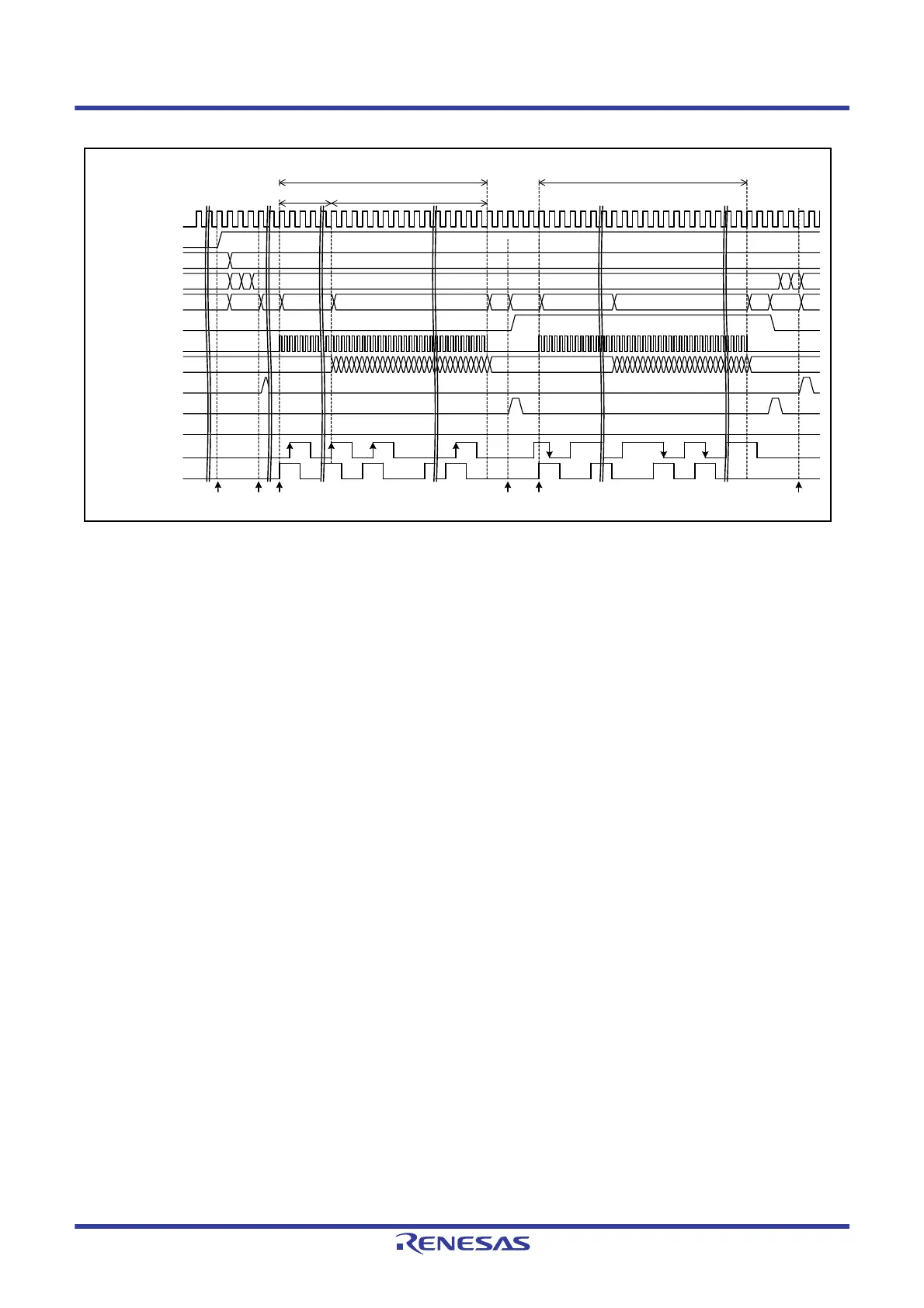
Figure 43.17 Timing Chart of Mutual Capacitance Full Scan Mode
(Measurement Start Condition is Software Trigger)
The following describes operation shown in the timing chart in Figure 43.17.
(1) After various settings are made, operation is started by writing 1 to the CTSUCR0.CTSUSTRT bit.
(2) After a channel to be measured is determined according to the preset conditions, a request for setting the
corresponding channel (CTSUWR) is output.
(3) Upon completion of writing the measurement channel settings (CTSUSSC, CTSUSO0, and CTSUSO1 registers),
the sensor drive pulse is output and the sensor ICO clock and the reference ICO clock operate.
At the same time, a pulse which is handled as the rising edge is output to the transmit pin on the measurement
channel during the high-level period of the sensor drive pulse.
(4) After the sensor stabilization wait time and the measurement time have elapsed and measurement is finished, a
measurement result read request (CTSURD) is output.
(5) The same channel is measured by outputting a pulse that is handled as the falling edge during the high-level period
of the sensor drive pulse.
(6) After the same channel is measured twice, a channel to be measured next is determined and measured in the similar
way.
(7) Upon completion of all measurement channels, a measurement end interrupt (CTSUFN) is output and measurement
is finished (transition to Status 0).
The mutual capacitance measurement status flag (CTSUST.CTSUPS flag) is changed when Status 5 transitions to Status
1.
CTSUST.CTSUPS flag
32
Measurement result
4 (During current/count value
conversion)
3
0
163 2 5
63
0
CTSUST.CTSUSTC[2:0]
flags (Status)
0 4 (During current/count value conversion) 251
Sensor drive pulse
Measurement time
Operating clock
CTSUCR0.CTSUSTRT bit
1
(1) (2) (4)
CTSUSC counter
3 4
Transmit pin state of
measurement channel
Measurement result
5
CTSUMCH1 register
(Transmit channel)
CTSUMCH0 register
(Receive channel)
(6)
CTSURD interrupt
CTSUWR interrupt
Sensor ICO clock
CTSUFN interrupt
0
(3) (5)
1
Measurement of rising edge Measurement of falling edge
Sensor stabilization wait time
(CTSUSST register)

 Loading...


