R01UH0823EJ0100 Rev.1.00 Page 601 of 1823
Jul 31, 2019
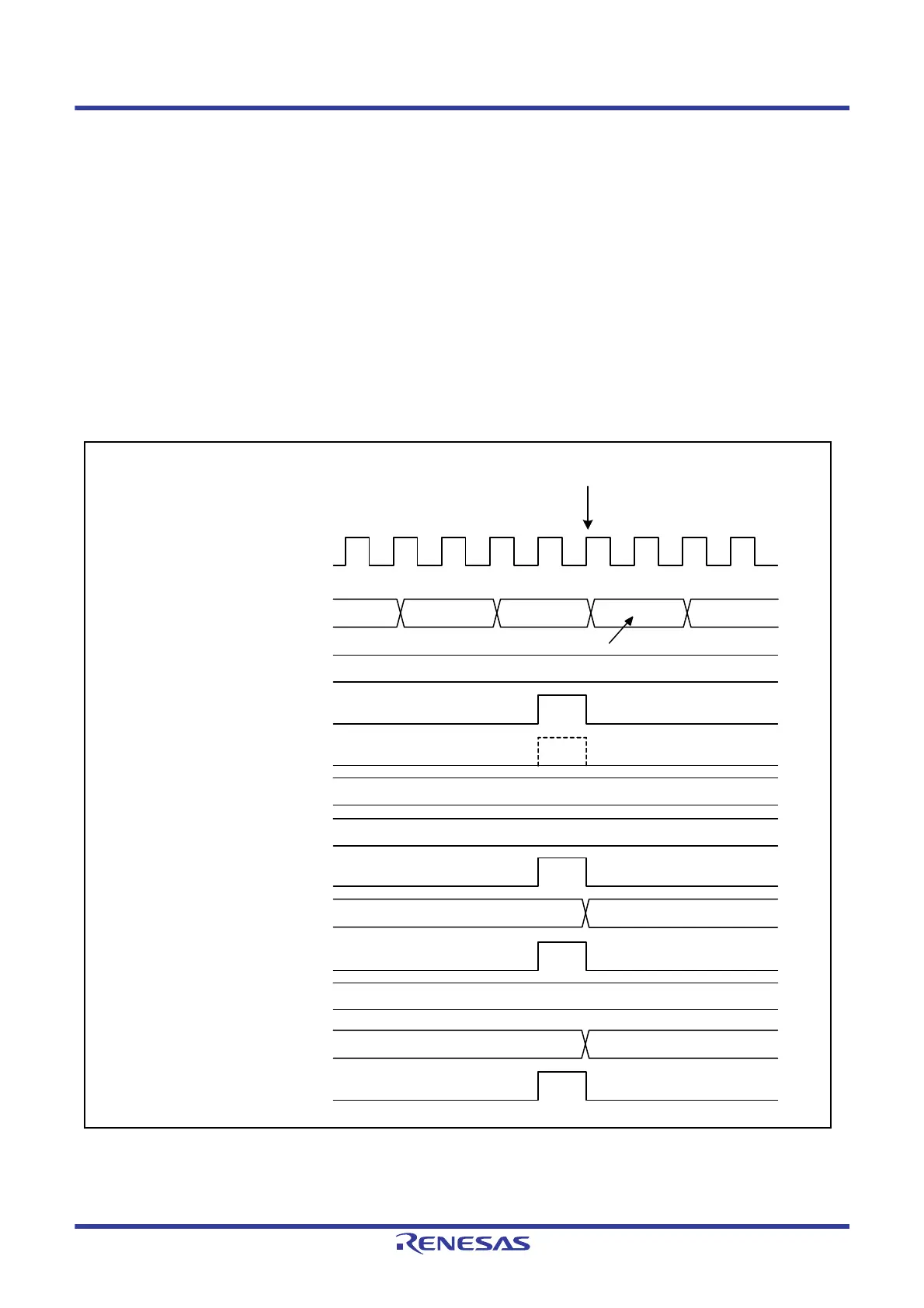
RX23W Group 23. Multi-Function Timer Pulse Unit 2 (MTU2a)
23.6.12 Contention between MTU2.TCNT Write Operation and Overflow/Underflow in
Cascaded Operation
With timer counters MTU1.TCNT and MTU2.TCNT in a cascade, when a contention occurs between MTU1.TCNT
counting (an MTU2.TCNT counter overflow/underflow) and the MTU2.TCNT write cycle, the MTU2.TCNT write
operation is performed and the MTU1.TCNT count signal is disabled. In this case, if the MTU1.TGRA register works as
a compare match register and there is a match between the MTU1.TGRA register and the MTU1.TCNT counter values,
a compare match signal is issued.
Furthermore, when the MTU1.TCNT count clock is selected as the input capture source of MTU0, registers
MTU0.TGRA to MTU0.TGRC work in input capture mode. In addition, when the MTU0.TGRC compare match/input
capture is selected as the input capture source of the MTU1.TGRB register, the MTU1.TGRB register works in input
capture mode.
Figure 23.105 shows the timing in this case.
When setting the TCNT clearing function in cascaded operation, be sure to synchronize MTU1 and MTU2.
Figure 23.105 Contention between MTU2.TCNT Write Operation and Overflow/Underflow in Cascaded Operation
MTU1.TCNT
MTU2.TCNT
MTU2.TGRA, TGRB
MTU2 compare match signal A/B
MTU1.TCNT count clock
MTU1.TGRA
MTU1 compare match signal A
MTU1.TGRB
MTU1 input capture signal B
MTU0.TCNT
MTU0.TGRA to TGRC
MTU0 input capture signal A to C
MTU2.TCNT write data
Written by CPU
FFFEh FFFFh N N + 1
FFFFh
M
M
N
P
QP
M
PCLK
Disabled

 Loading...


