R01UH0823EJ0100 Rev.1.00 Page 415 of 1823
Jul 31, 2019
RX23W Group 20. Event Link Controller (ELC)
20.2.3 Event Link Option Setting Register A (ELOPA)
Note 1. The MTU1.TCNT value is captured into the MTU1.TGRA register.
Note 2. The MTU2.TCNT value is captured into the MTU2.TGRA register.
Note 3. The MTU3.TCNT value is captured into the MTU3.TGRA register.
The ELOPA register specifies the operations of MTU1 to MTU3 when an event signal is input. Set 11b (event output is
disabled) when the ELC function is not used.
20.2.4 Event Link Option Setting Register B (ELOPB)
Note 1. The MTU4.TCNT value is captured into the MTU4.TGRA register.
The ELOPB register specifies the operation of MTU4 when an event signal is input. Set 11b (event output is disabled)
when the ELC function is not used.
Address(es): ELC.ELOPA 0008 B11Fh
b7 b6 b5 b4 b3 b2 b1 b0
MTU3MD[1:0] MTU2MD[1:0] MTU1MD[1:0] — —
Value after reset:
11111111
Bit Symbol Bit Name Description R/W
b1, b0 — Reserved These bits are read as 1. The write value should be 1. R/W
b3, b2 MTU1MD[1:0] MTU1 Operation Select
b3 b2
0 0: Counting is started.
0 1: Counting is restarted.
1 0: Input capture
*1
1 1: Event output is disabled.
R/W
b5, b4 MTU2MD[1:0] MTU2 Operation Select
b5 b4
0 0: Counting is started.
0 1: Counting is restarted.
1 0: Input capture
*2
1 1: Event output is disabled.
R/W
b7, b6 MTU3MD[1:0] MTU3 Operation Select
b7 b6
0 0: Counting is started.
0 1: Counting is restarted.
1 0: Input capture
*3
1 1: Event output is disabled.
R/W
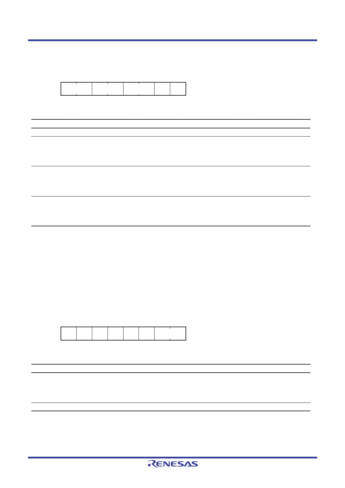
Address(es): ELC.ELOPB 0008 B120h
b7 b6 b5 b4 b3 b2 b1 b0
——————MTU4MD[1:0]
Value after reset:
11111111
Bit Symbol Bit Name Description R/W
b1, b0 MTU4MD[1:0] MTU4 Operation Select
b1 b0
0 0: Counting is started.
0 1: Counting is restarted.
1 0: Input capture
*1
1 1: Event output is disabled.
R/W
b7 to b2 — Reserved These bits are read as 1. The write value should be 1. R/W

 Loading...


