R01UH0823EJ0100 Rev.1.00 Page 1656 of 1823
Jul 31, 2019
RX23W Group 48. Data Operation Circuit (DOC)
48.3.3 Data Subtraction Mode
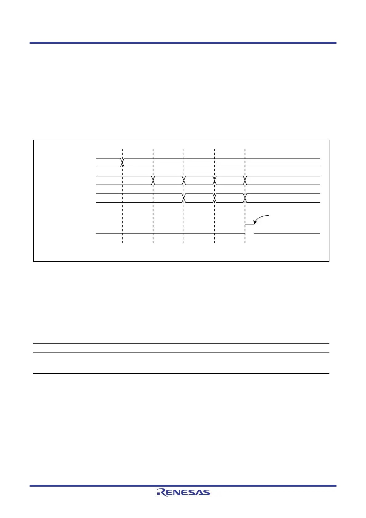
Figure 48.4 shows an example of the steps involved in data subtraction mode operation by the data operation circuit.
(1) Writing 10b to the DOCR.OMS[1:0] bits selects data subtraction mode.
(2) 16-bit data is set in the DODSR register as the initial value.
(3) 16-bit data to be subtracted is written to DODIR. The result of the operation is stored in DODSR.
(4) Writing of 16-bit data continues until all data for subtraction have been written to DODIR.
(5) If the result of an operation is less than 0000h, the DOCR.DOPCF flag is set to 1. When the DOCR.DOPCIE bit is
1, a data operation circuit interrupt is also generated.
Figure 48.4 Example of Operation in Data Subtraction Mode
48.4 Interrupt Requests
The data operation circuit generates the data operation circuit interrupt as an interrupt request. When an interrupt source
is generated, the data operation circuit flag corresponding to the interrupt is set to 1.
Table 48.2 describes the interrupt
request.
Table 48.2 Interrupt Request from Data Operation Circuit
Interrupt Request Data Operation Circuit Flag Interrupt Generation Timing
Data operation circuit
interrupt
DOPCF The compared values either match or mismatch
The result of data addition is greater than FFFFh
The result of data subtraction is less than 0000h
DODIR register
1
0
DODSR register
DOCR.OMS[1:0] bits
(1)
(2) (3) (4)
Write 1 to
DOCR.DOPCFCL bit
(5)
10bxxb
FFFDhxxxxh 000Fh 000Bh 0005h
0008hxxxxh 0004h 0006h
DOCR.DOPCF flag
 Loading...


