R01UH0823EJ0100 Rev.1.00 Page 754 of 1823
Jul 31, 2019
RX23W Group 27. Compare Match Timer (CMT)
27. Compare Match Timer (CMT)
This MCU has two on-chip compare match timer (CMT) units (unit 0 and unit 1), each consisting of a two-channel 16-bit
timer (i.e., a total of four channels). The CMT has a 16-bit counter, and can generate interrupts at set intervals.
In this section, “PCLK” is used to refer to PCLKB.
27.1 Overview
Table 27.1 lists the specifications for the CMT.
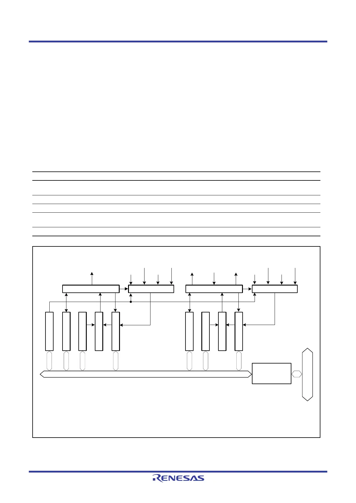
Figure 27.1 shows a block diagram of the CMT (unit 0). A two-channel CMT constitutes a unit. Unit 0 and unit 1 are the
same in terms of specifications. Compare match timer start register 0 (CMSTR0) and compare match interrupts (CMI0
and CMI1) of unit 0 correspond to compare match timer start register 1 (CMSTR1) and compare match interrupts (CMI2
and CMI3) of unit 1.
Figure 27.1 CMT (Unit 0) Block Diagram
Table 27.1 CMT Specifications
Item Description
Count clocks Four frequency dividing clocks
One clock from PCLK/8, PCLK/32, PCLK/128, and PCLK/512 can be selected for each channel.
Interrupt A compare match interrupt can be requested for each channel.
Event link function (output) An event signal is output upon a CMT1 compare match.
Event link function (input) Linking to the specified module is possible.
CMT1 count start, event counter, or count restart operation is possible.
Low power consumption function Each unit can be placed in a module stop state.
Control circuit Clock selection
Module bus
CMI0
PCLK/32 PCLK/512
PCLK/128
PCLK/8
Control circuit Clock selection
Event
signal
input
*1
PCLK/32 PCLK/512
PCLK/128
PCLK/8
Bus interface
Comparator
Comparator
Internal peripheral bus
CMSTR0: Compare match timer start register 0
CMCR: Compare match timer control register
CMCOR: Compare match timer constant register
CMCNT: Compare match timer counter
CMI: Compare match interrupt
CMSTR0
CMCR
CMCOR
CMCNT
CMCR
CMCOR
CMCNT
CMI1
Event
signal
output
*1
Note 1. Event signal input and output are available for CMT1 only.

 Loading...


