R01UH0823EJ0100 Rev.1.00 Page 387 of 1823
Jul 31, 2019
RX23W Group 19. Data Transfer Controller (DTCa)
19.2.10 DTC Module Start Register (DTCST)
DTCST Bit (DTC Module Start)
Set the DTCST bit to 1 to enable the DTC to accept transfer requests. When this bit is set to 0, transfer requests are no
longer accepted.
If this bit is set to 0 during data transfer, the accepted transfer request is active until the processing is completed.
Set the DTCST bit to 0 before making a transition to the module stop state, deep sleep mode, or software standby mode.
Set the DTCST bit to 1 to resume the data transfer after returning from the module stop state, deep sleep mode, or
software standby mode.
For details on transitions to the module stop state, deep sleep mode, and software standby mode, refer to
section 19.9,
Low Power Consumption Function
, and section 11, Low Power Consumption.
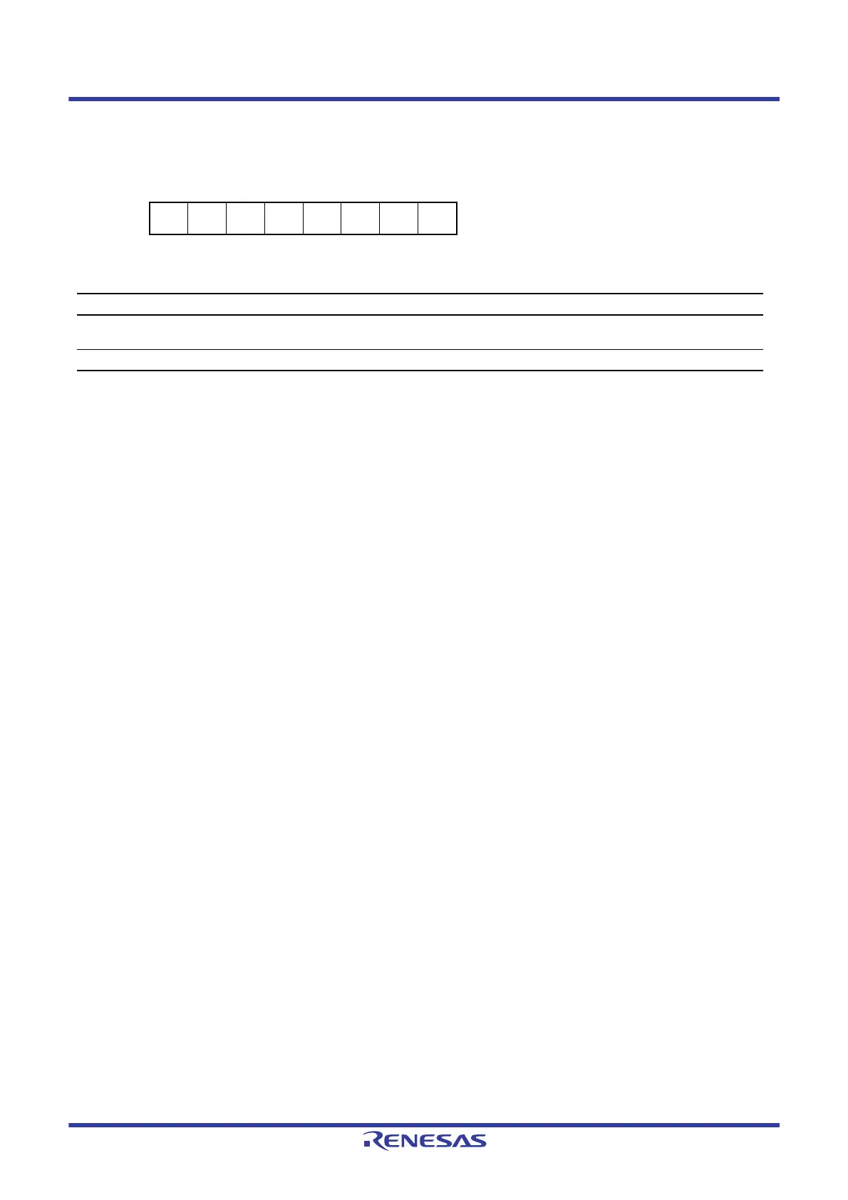
Address(es): DTC.DTCST 0008 240Ch
b7 b6 b5 b4 b3 b2 b1 b0
———————DTCST
Value after reset:
00000000
Bit Symbol Bit Name Description R/W
b0 DTCST DTC Module Start 0: DTC module stop
1: DTC module start
R/W
b7 to b1 — Reserved These bits are read as 0. The write value should be 0. R/W

 Loading...


