R01UH0823EJ0100 Rev.1.00 Page 1492 of 1823
Jul 31, 2019
RX23W Group 43. Capacitive Touch Sensing Unit (CTSU)
43.2 Register Descriptions
43.2.1 CTSU Control Register 0 (CTSUCR0)
Note 1. The CTSUSC, CTSURC, CTSUMCH0, CTSUMCH1, and CTSUST registers are initialized.
The CTSUCAP and CTSUSNZ bits should be set when the CTSUSTRT bit is 0. These bits can be set at the same time as
starting measurement operation.
CTSUSTRT Bit (CTSU Measurement Operation Start)
This bit specifies whether CTSU operation starts or stops.
When the CTSUCAP bit is 0 (software trigger), measurement is started by writing 1 to the CTSUSTRT bit, and the
CTSUSTRT bit becomes 0 when measurement is finished.
When the CTSUCAP bit is 1 (external trigger), the CTSU waits for an external trigger by writing 1 to the CTSUSTRT
bit, and measurement is started at the rising edge of the external trigger. When measurement is finished, the CTSU waits
for the next external trigger and operation is continued.
Table 43.3 lists the CTSU states.
Note 1. The state can be read from the CTSUST.CTSUSTC[2:0] flags.
During measurement: CTSUST.CTSUSTC[2:0] flags ≠ 000b
Wait for an external trigger: CTSUST.CTSUSTC[2:0] flags = 000b
If the CTSUSTRT bit is set to 1 when the CTSUSTRT bit is 1, writing is ignored and operation is continued.
To forcibly stop operation (forced stop) when the CTSUSTRT bit is 1, set the CTSUSTRT bit to 0 and the CTSUINIT bit
to 1 simultaneously.
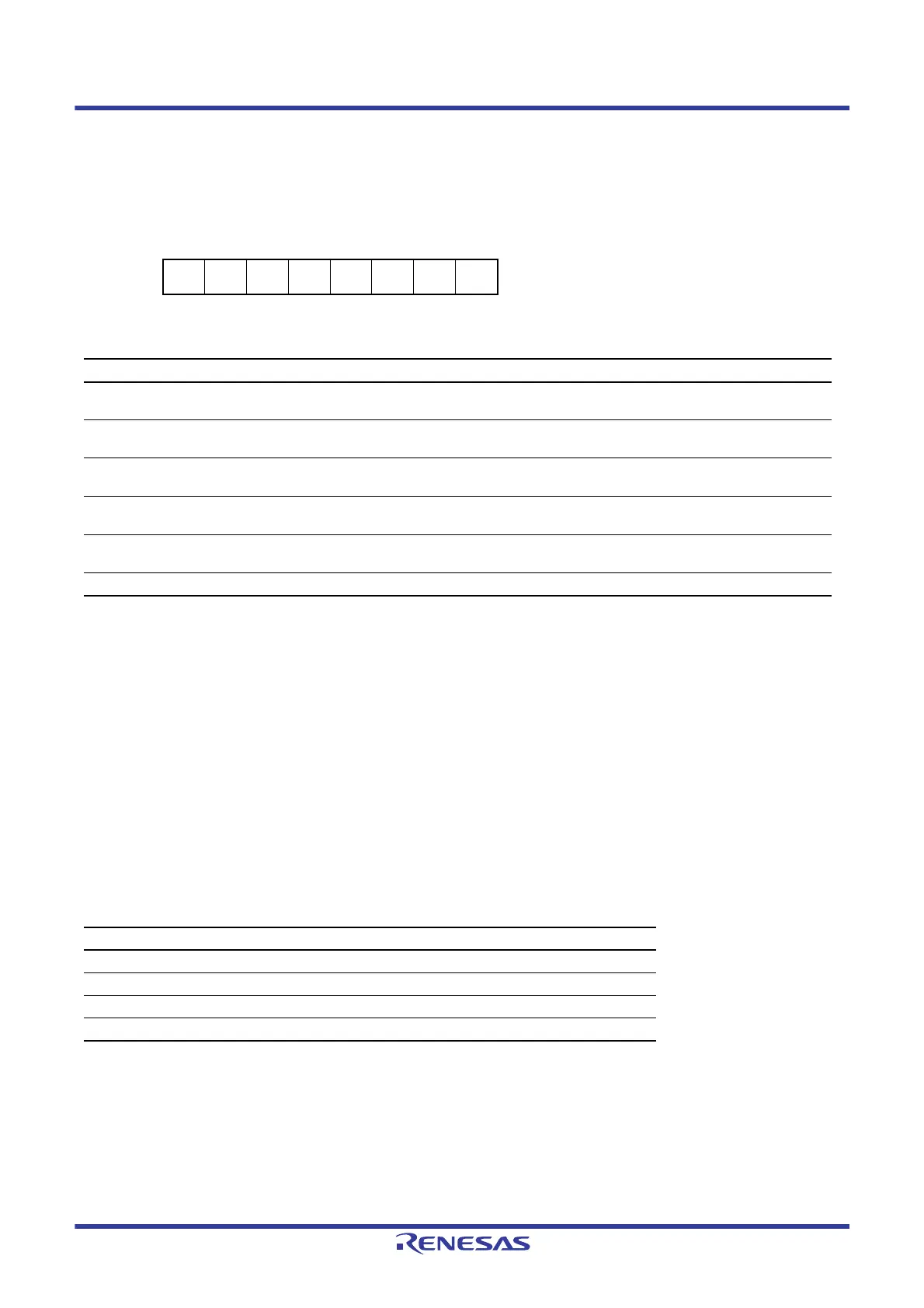
Address(es): CTSU.CTSUCR0 000A 0900h
b7 b6 b5 b4 b3 b2 b1 b0
———
CTSUI
NIT
CTSUI
OC
CTSUS
NZ
CTSUC
AP
CTSUS
TRT
Value after reset:
00000000
Bit Symbol Bit Name Description R/W
b0 CTSUSTRT CTSU Measurement Operation Start 0: Measurement operation stops
1: Measurement operation starts
R/W
b1 CTSUCAP CTSU Measurement Operation Start
Trigger Select
0: Software trigger
1: External trigger
R/W
b2 CTSUSNZ CTSU Wait State Power-Saving
Enable
0: Power-saving function during wait state is disabled
1: Power-saving function during wait state is enabled
R/W
b3 CTSUIOC CTSU Transmit Pin Control 0: The TS pins are driven low
1: The TS pins are driven high
R/W
b4 CTSUINIT CTSU Control Block Initialization Writing 1 to this bit initializes the CTSU control block
and registers*
1
. This bit is read as 0.
R/W
b7 to b5 — Reserved These bits are read as 0. The write value should be 0. R/W
Table 43.3 CTSU States
CTSUSTRT Bit CTSUCAP Bit CTSU State
0 0 Stopped
0 1 Stopped
1 0 During measurement
1 1 During measurement/wait for an external trigger*
1

 Loading...


