R01UH0823EJ0100 Rev.1.00 Page 1408 of 1823
Jul 31, 2019
RX23W Group 38. Serial Peripheral Interface (RSPIa)
38.3.13 Self-Diagnosis of Parity Bit Function
The parity circuit consists of a parity bit adding unit used for transmit data and an error detecting unit used for received
data. In order to detect defects in the parity bit adding unit and error detecting unit of the parity circuit, self-diagnosis is
executed for the parity circuit following the flowchart shown in
Figure 38.49.
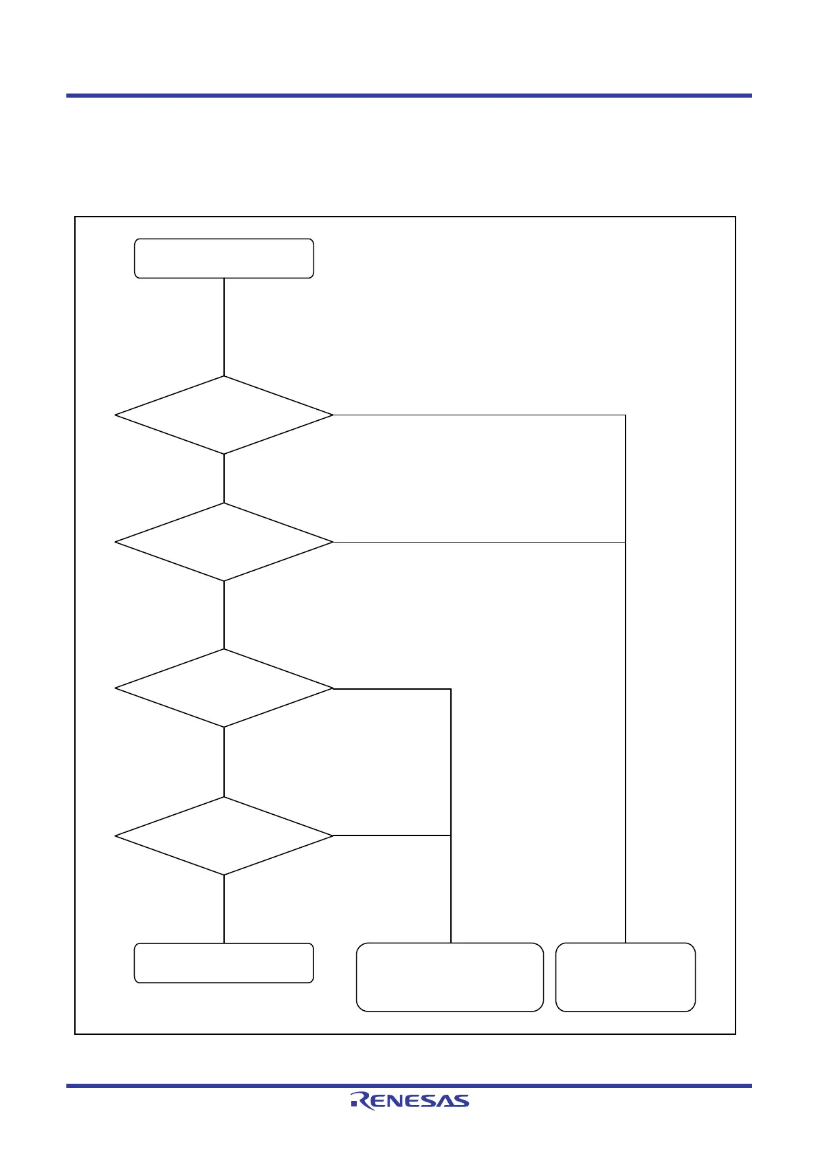
Figure 38.49 Flowchart for Self-Diagnosis of Parity Circuit
Start of self-diagnosis of
parity circuit
Add incorrect parity bit to
transmit data and transfer it
Loopback operation with
the parity bit added at
normal operation
Check the data that is stored in
the transmit data register
Normal end
No defect in parity circuit
Erroneous end
Defect found in parity bit adding unit
No defect in error detecting unit
Erroneous end
Defect found in error
detecting unit
Select full-duplex synchronous serial communications (SPCR.TXMD = 0).
Enable the parity circuit self-diagnosis function (SPCR2.PTE = 1).
Enable the parity function (SPCR2.SPPE = 1).
Select loopback mode (SPPCR.SPLP2 = 1).
Parity error occurred
No parity error
No parity error
Parity error occurred
Disable the parity circuit self-diagnosis function (SPCR2.PTE = 0).
Parity error occurred
No parity error
Correct parity bit is added
Incorrect parity bit is
added
Add correct parity bit to
transmit data and transfer it

 Loading...


