R01UH0823EJ0100 Rev.1.00 Page 1517 of 1823
Jul 31, 2019
RX23W Group 43. Capacitive Touch Sensing Unit (CTSU)
43.3.2.2 Status Counter
The measurement status counter of the CTSU status register (CTSUST) indicates the current measurement status. The
measurement status is common to all four modes.
Figure 43.11 shows status operation transitions.
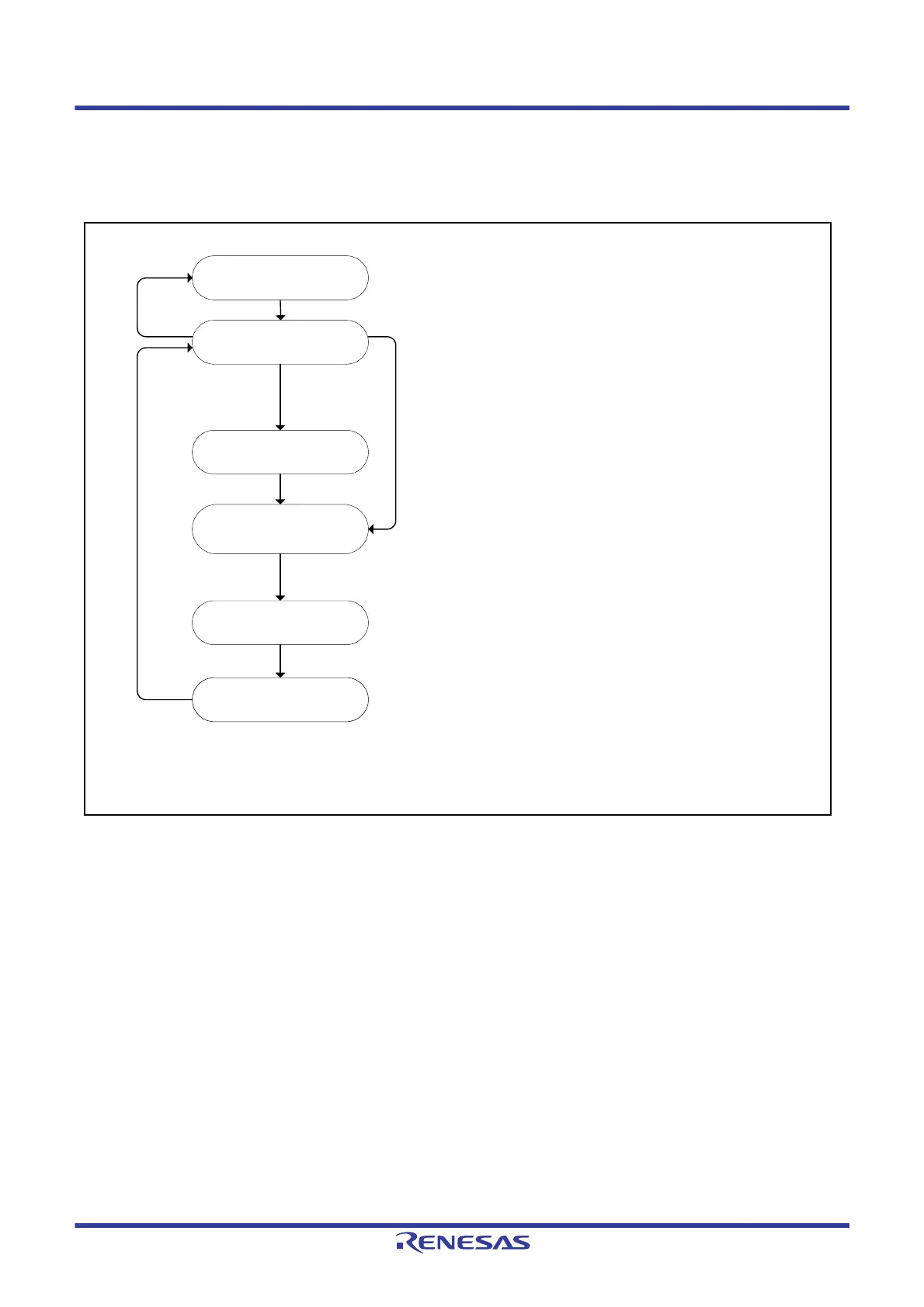
Figure 43.11 Status Operation Transitions
The status of the status counter transitions to Status 0 when all of the specified measurement channels are measured.
The CTSUCR0.CTSUSTRT bit is cleared to 0 by hardware when a software trigger is used. When an external trigger is
used, the value 1 is retained, and the CTSU waits for the next trigger.
When operation is forcibly stopped (by writing 0 to the CTSUCR0.CTSUSTRT bit and 1 to CTSUCR0.CTSUINIT bit at
the same time) during measurement or the wait state for the trigger, the status transitions to Status 0 and measurement is
stopped forcibly.
If there is no channel to be measured by setting the CTSUMCH0, CTSUCHACn, CTSUCHAC4, CTSUCHTRCn, and
CTSUCHTRC4 registers (n = 0 to 3), a CTSUFN interrupt is generated immediately after a transition to Status 1, and
then the status transitions to Status 0. The following are the cases when there is no channel to be measured.
A measurement target channel is not specified by the CTSUCHACn and CTSUCHAC4 registers.
In self-capacitance single scan mode, the channel specified in the CTSUMCH0 register is not a measurement target
in the CTSUCHACn and CTSUCHAC4 registers.
In full scan mode, there is no transmit channel or receive channel to be measured by combining the CTSUCHACn,
CTSUCHAC4, CTSUCHTRCn, and CTSUCHTRC4 registers.
Status 0
Stopped/wait for external trigger
Status1
Measurement channel update/
determination of measurement finish
Status 2
Wait for sensor drive pulse setting
Status 4
Measurement start/
measurement period
Conditions for transition to Status 1
• CTSUCR0.CTSUCAP bit = 0: CTSUCR0.CTSUSTRT bit = 1
• CTSUCR0.CTSUCAP bit = 1: CTSUCR0.CTSUSTRT bit = 1 and
the rising edge of the external trigger is detected
Status 5
Measurement completed
Status 3
Sensor drive pulse output start/
sensor stabilization wait period*
2
Condition for transition to Status 0
• There is no channel to be measured next
(A CTSUFN interrupt is generated and measurement is finished)
Condition for transition to Status 2
• Update of the measurement channel is completed
Condition for transition to Status 3
• CTSUST.CTSUPS flag = 1 (second measurement) in mutual capacitance
full scan mode
Condition for transition to Status 3
• Write access to the CTSUSO1 register*
1
Condition for transition to Status 4
• CTSUST.CTSUDTSR flag = 0 when the sensor stabilization has elapsed
after supply of the sensor drive pulse starts
Condition for transition to Status 5
• The measurement time has elapsed after measurement is started
For details on the measurement time, refer to the Sensor Stabilization Wait
Time and Measurement Time in the Capacitive Touch Sensor (CTSU)
section.
Condition for transition to Status 1
• After two clocks of the operating clock have elapsed
Note 1. When using the DTC/ICU to set the registers in the CTSUWR interrupt
handling, write to the CTSUSO1 register last.
Note 2. If the CTSUST.CTSUDTSR flag is 1, wait until the previous measurement
result is transferred.
 Loading...


