R01UH0823EJ0100 Rev.1.00 Page 1407 of 1823
Jul 31, 2019
RX23W Group 38. Serial Peripheral Interface (RSPIa)
38.3.12 Loopback Mode
When 1 is written to the SPPCR.SPLP2 bit or SPPCR.SPLP bit, the RSPI shuts off the path between the MISOA pin and
the shift register if the SPCR.MSTR bit is 1, and between the MOSIA pin and the shift register if the SPCR.MSTR bit is
0, and connects the input path and output path of the shift register. The RSPI does not shut off the path between the
MOSIA pin and the shift register if the SPCR.MSTR bit is 1, and between the MISOA pin and the shift register if the
SPCR.MSTR bit is 0. This is called loopback mode. When a serial transfer is executed in loopback mode, the transmit
data for the RSPI or the reversed transmit data becomes the received data for the RSPI.
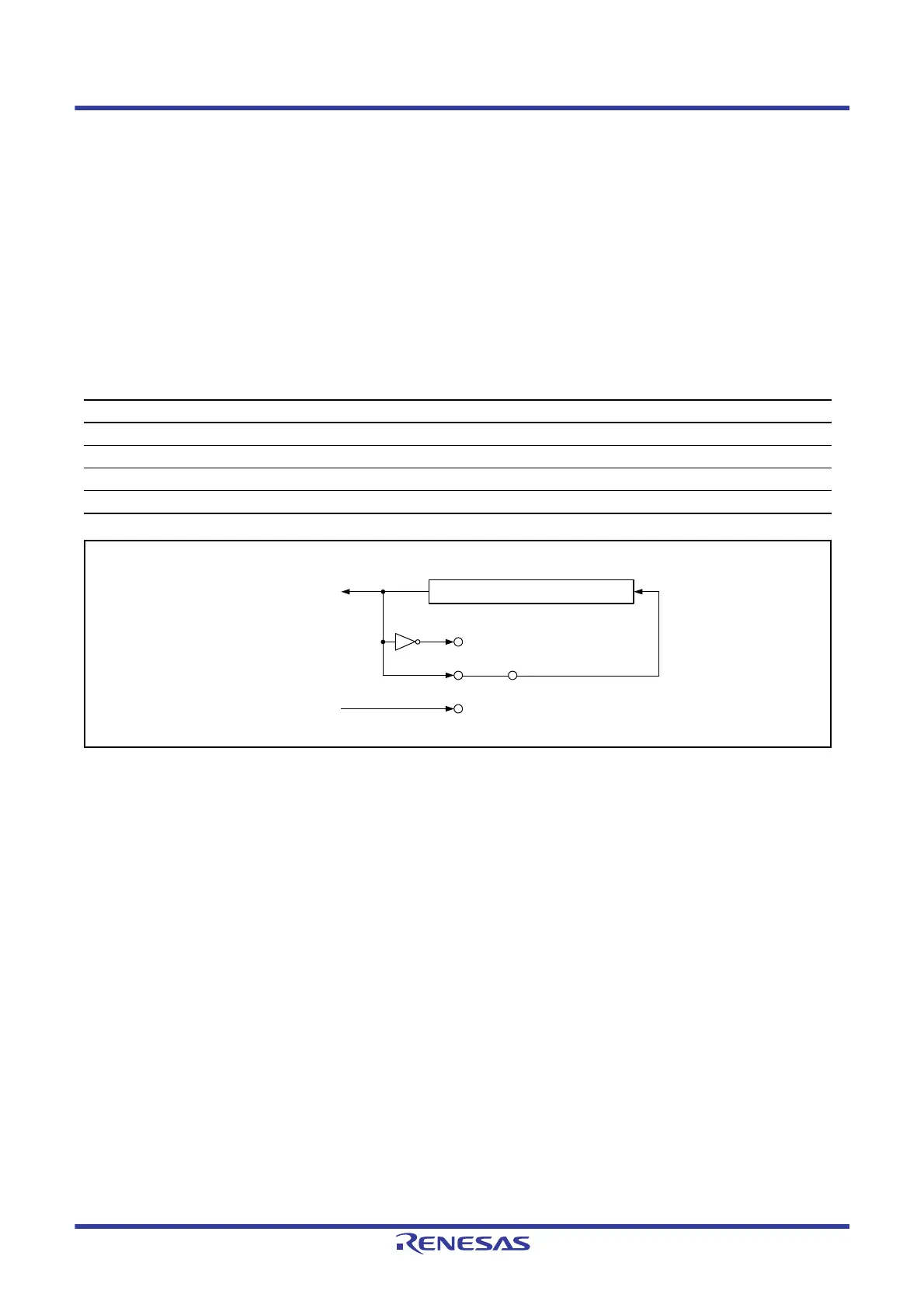
Table 38.12 lists the relationship among the SPLP2 and SPLP bits and the received data. Figure 38.48 shows the
configuration of the shift register I/O paths for the case where the RSPI in master mode is set in loopback mode
(SPPCR.SPLP2 = 0, SPPCR.SPLP = 1).
Figure 38.48 Configuration of Shift Register I/O Paths in Loopback Mode (Master Mode)
Table 38.12 SPLP2 and SPLP Bit Settings and Received Data
SPPCR.SPLP2 Bit SPPCR.SPLP Bit Received Data
0 0 Input data from the MOSIA pin or MISOA pin
0 1 Inverted transmit data
1 0 Transmit data
1 1 Transmit data
Shift register
Loopback
Loopback 2
Normal
Transmission
Reception
(MOSIA/MISOA)
(MISOA/MOSIA)

 Loading...


