R01UH0823EJ0100 Rev.1.00 Page 301 of 1823
Jul 31, 2019
RX23W Group 15. Interrupt Controller (ICUb)
15.4.7 Digital Filter
The digital filter function is provided for the external interrupt request IRQi pins (i = 0, 1, and 4 to 7) and NMI pin
interrupt.
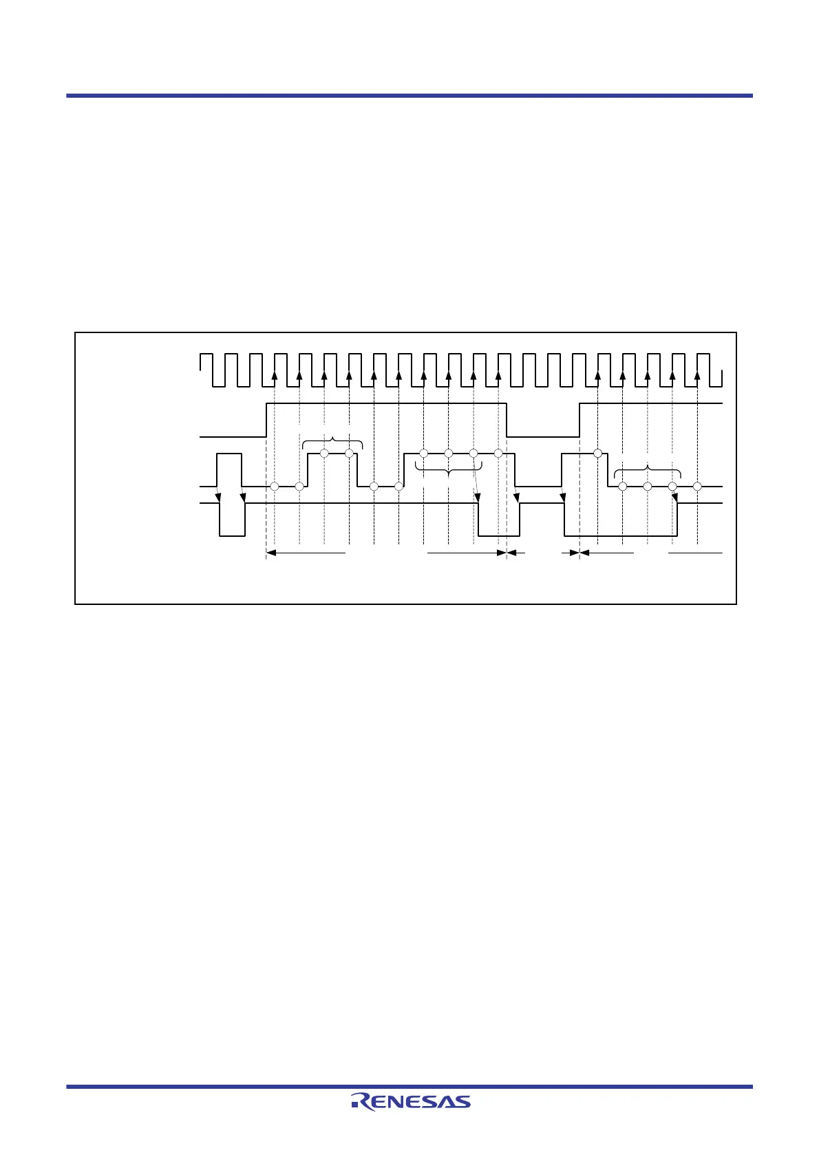
The digital filter samples input signals at the filter sampling clock (PCLK) and removes the pulses of which length is less
than three sampling cycles.
To use the digital filter for the IRQi pin, set the sampling clock cycle (PCLK, PCLK/8, PCLK/32, or PCLK/64) with the
IRQFLTC0.FCLKSELi[1:0] bits and set the IRQFLTE0.FLTENi bit to 1 (digital filter enabled).
To use the digital filter for the NMI pin, set the sampling clock cycle (PCLK, PCLK/8, PCLK/32, or PCLK/64) with the
NMIFLTC.NFCLKSEL[1:0] bits and set the NMIFLTE.NFLTEN bit to 1 (digital filter enabled).
Figure 15.8 shows an example of digital filter operation.
Figure 15.8 Digital Filter Operation Example
Before software standby mode is entered, set the IRQFLTE0.FLTENi and NMIFLTE.NFLTEN bits to 0 (digital filter
disabled). To use the digital filter again after return from software standby mode, set the IRQFLTE0.FLTENi or
NMIFLTE.NFLTEN bit to 1 (digital filter enabled).
15.4.8 External Pin Interrupts
The procedure for using the signal on an external pin as an interrupt is as follows.
1. Clear the IERm.IENj bit (m = 02h to 1Fh, j = 0 to 7) to 0 (interrupt request disabled).
2. Clear the IRQFLTE0.FLTENi bit (i = 0, 1, and 4 to 7) to 0 (digital filter disabled).
*
1
3. Set the digital filter sampling clock with the IRQFLTC0.FCLKSELi[1:0] bits.*
1
4. Make or confirm the I/O port settings.
5. Set the method of detection for the interrupt in the IRQCRi.IRQMD[1:0] bits.
6. Clear the corresponding IRn.IR flag (n = interrupt vector number) to 0 (if edge detection is in use).
7. Set the IRQFLTE0.FLTENi bit to 1 (digital filter enabled).
*
1
8. If the interrupt is to be used for DMAC trigger, set the DMRSRm.DMRS[7:0] bits. If the interrupt is to be used for
DTC trigger, set the DTCERn.DTCE bit. The interrupt will be a CPU interrupt if neither of these settings is made.
9. Set the IERm.IENj bit to 1 (interrupt request enabled).
Note 1. To use the digital filter function, settings must be made beforehand.
Sampling clock
for digital filter
IRQFLTE0.FLTENi bit
IRQi pin
IRn.IR flag
Digital filter enabled EnabledDisabled
The level matches
three times
The level matches
three times
Pulses removed
Operation example with IRQCRi.IRQMD[1:0] = 00b (low level)
 Loading...


