R01UH0823EJ0100 Rev.1.00 Page 1700 of 1823
Jul 31, 2019
RX23W Group 50. Flash Memory (FLASH)
50.8 Boot Mode
The USB interface, SCI, or FINE interface is used in boot mode.
Table 50.6 lists the Programmable and Erasable Areas and Peripheral Modules Used in Boot Mode. Table 50.7 lists the
I/O Pins Used in Boot Mode.
Note 1. When using the SCI, connect (pull up) this pin to VCC via a resistor.
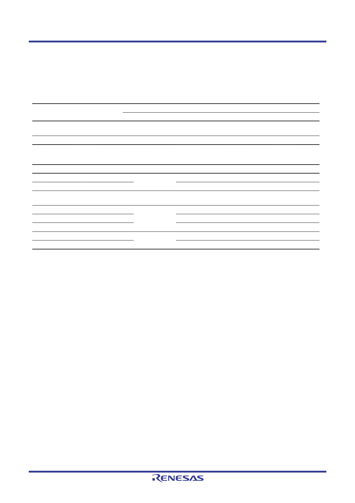
Table 50.6 Programmable and Erasable Areas and Peripheral Modules Used in Boot Mode
Item
Boot Mode
USB Interface SCI Interface FINE Interface
Programmable and erasable areas User area
Data area
User area
Data area
User area
Data area
Peripheral module USB0 SCI1 (asynchronous serial communication) FINE
Table 50.7 I/O Pins Used in Boot Mode
Pin Name I/O Mode Description
PC7/UB Input Boot mode Select operating mode (refer to section 3, Operating Modes).
MD Input Select operating mode (refer to section 3, Operating Modes).
MD/FINED I/O Boot mode
(FINE interface)
Select operating mode/FINE data I/O
USB0_DP, USB0_DM I/O Boot mode
(USB interface)
USB data I/O
P16/USB0_VBUS Input Detect USB cable connection/disconnection
P35/UPSEL Input Set bus-powered mode or self-powered mode
P30/RXD1 Input Boot mode
(SCI interface)
Receive data*
1
P26/TXD1 Output Transmit data*
1

 Loading...


