R01UH0823EJ0100 Rev.1.00 Page 89 of 1823
Jul 31, 2019
RX23W Group 2. CPU
2.6.2 Interrupt Vector Table
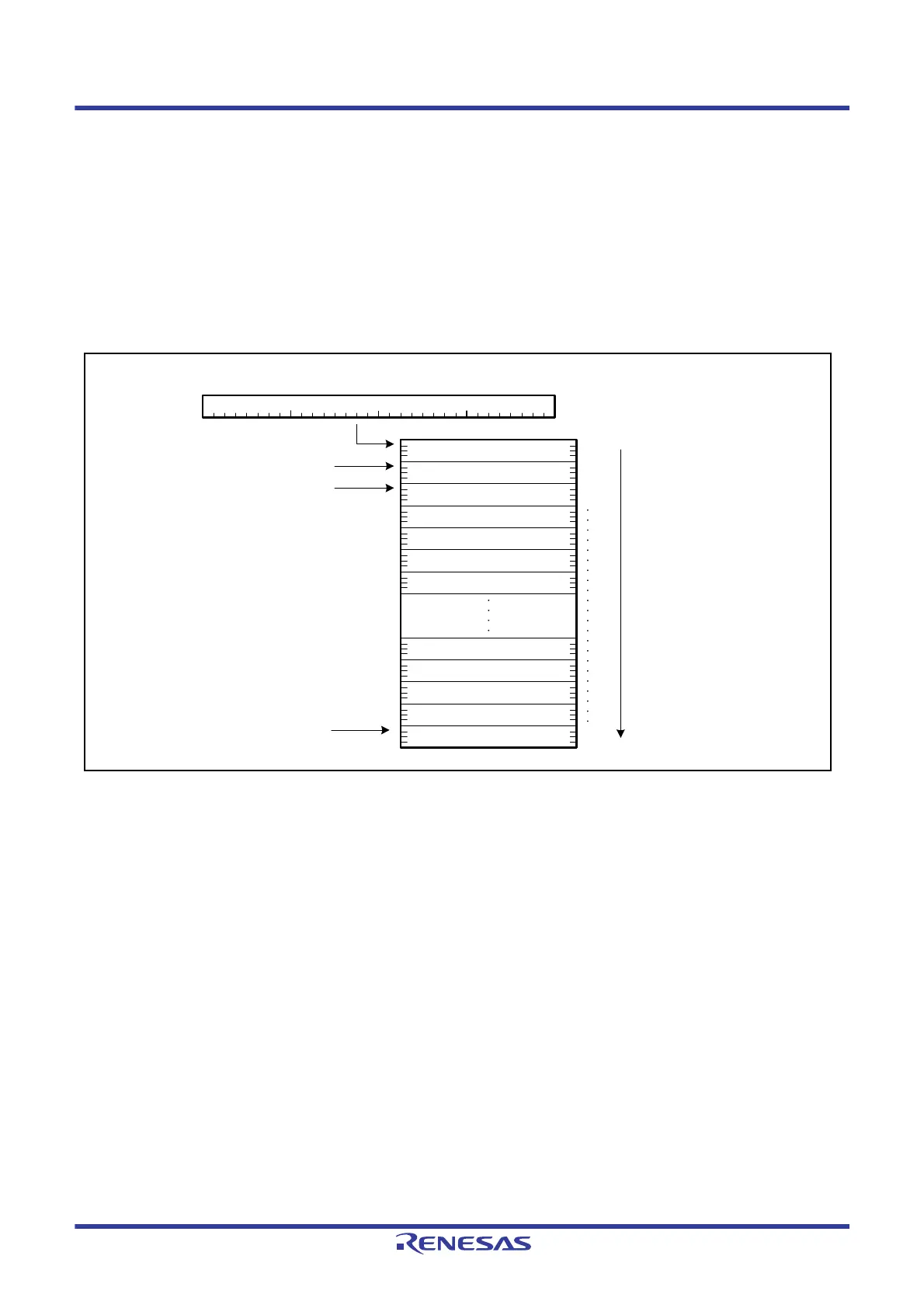
The address where the interrupt vector table is placed can be adjusted. The table is a 1,024-byte region that contains all
vectors for unconditional traps and interrupts and starts at the address (IntBase) specified in the interrupt table register
(INTB).
Figure 2.9 shows the interrupt vector table.
Each vector in the interrupt vector table has a vector number from 0 to 255. Each of the INT instructions, which act as the
sources of unconditional traps, is allocated to the vector that has the same number as is specified as the operand of the
instruction itself (from 0 to 255). The BRK instruction is allocated to the vector with number 0. Furthermore, vector
numbers (from 0 to 255) are allocated to interrupt requests in a fixed way for each product. For more on interrupt vector
numbers, see
section 15.3.1, Interrupt Vector Table.
Figure 2.9 Interrupt Vector Table
INTB
0
IntBase + 4
IntBase
b31 b0
IntBase + 8
255
IntBase + 1020
Interrupt vectors are
allocated in this order.
1
2

 Loading...


