R01UH0823EJ0100 Rev.1.00 Page 144 of 1823
Jul 31, 2019
RX23W Group 6. Resets
6.3.3 Voltage Monitoring 1 Reset
The voltage monitoring 1 reset is internal resets generated by the voltage monitoring circuit.
When the voltage monitoring 1 interrupt/reset enable bit (LVD1RIE) is set to 1 (enabling generation of a reset or
interrupt by the voltage detection circuit) and the voltage monitoring 1 circuit mode select bit (LVD1RI) is set to 1
(selecting generation of a reset in response to detection of a low voltage) in the voltage monitoring 1 circuit control
register 0 (LVD1CR0), the RSTSR0.LVD1RF flag is set to 1 and the voltage-detection circuit generates a voltage
monitoring 1 reset if VCC falls to or below Vdet1.
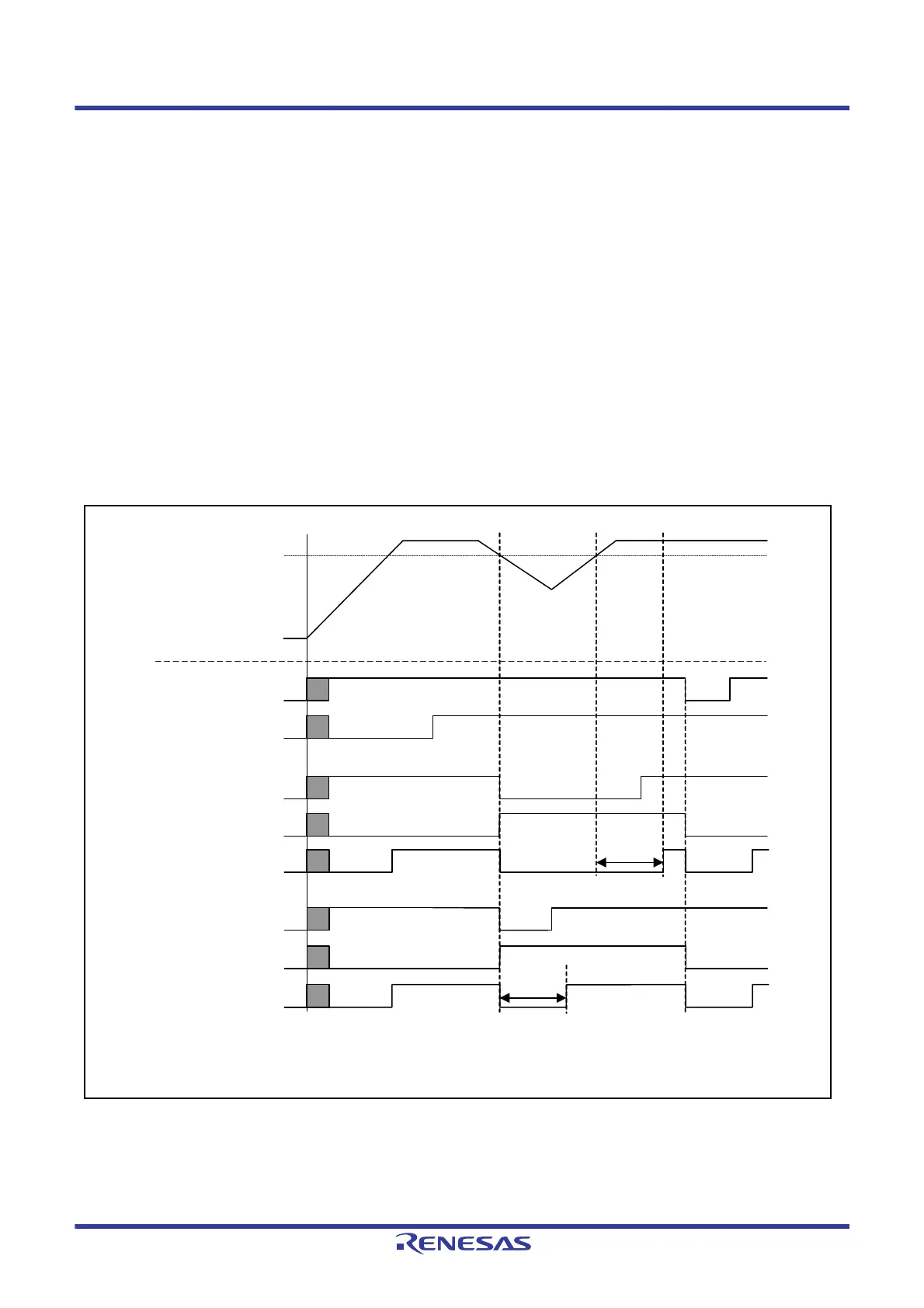
Timing for release from the voltage monitoring 1 reset state is selectable with the voltage monitoring 1 reset negation
select bit (LVD1RN) in the LVD1CR0 register. When the LVD1CR0.LVD1RN bit is 0 and VCC has fallen to or below
Vdet1, the CPU is released from the internal reset state and starts reset exception handling once the voltage monitoring 1
reset time (tLVD1) has elapsed after VCC has risen above Vdet1. When the LVD1CR0.LVD1RN bit is 1 and VCC has
fallen to or below Vdet1, the CPU is released from the internal reset state and starts reset exception handling once the
voltage monitoring 1 reset time (tLVD1) has elapsed.
Detection levels Vdet1 can be changed by settings in the voltage detection level select register (LVDLVLR).
Figure 6.2 shows examples of operations during voltage monitoring 1 reset.
For details on the voltage monitoring 1 reset, refer to
section 8, Voltage Detection Circuit (LVDAb).
Figure 6.2 Operation Examples During Voltage Monitoring 1 Reset
External voltage
VCC
Vdet1*
1
RES# pin
Voltage detection 1
signal (Low is valid)
tLVD1*
2
RES# pin reset
RSTSR0.LVD1RF
tLVD1*
2
RES# pin reset
RSTSR0.LVD1RF
LVCMPCR.LVD1E
LVD1 valid setting
LVD1CR0.LVD1RN = 0
LVD1CR0.LVD1RN = 1
Voltage detection 1
signal (Low is valid)
Internal reset signal
Internal reset signal
Note: For details on the electrical characteristics, see the Electrical Characteristics section.
Note 1. Vdet1 shows a detection level of voltage monitoring 1 reset.
Note 2. tLVD1 shows a time for voltage monitoring 1 reset.

 Loading...


