R01UH0823EJ0100 Rev.1.00 Page 1103 of 1823
Jul 31, 2019
RX23W Group 33. Serial Communications Interface (SCIg, SCIh)
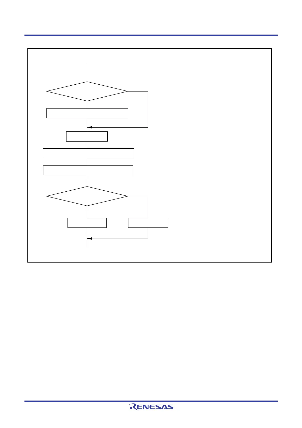
Figure 33.80 Example of Flowchart for Transition to Software Standby Mode during Reception
33.14.10 External Clock Input in Clock Synchronous Mode and Simple SPI Mode
In clock synchronous mode and simple SPI mode, the external clock SCKn must be input as follows:
High-pulse period, low-pulse period = 2 PCLK cycles or more, period = 6 PCLK cycles or more
Start data reception
Initialization
SCR.RE = 1
SCR.RE = 0
Read receive data in RDR
Make transition to software standby mode
Cancel software standby mode
No
No
Yes
Yes
RXI interrupt
Change operating mode?
Data reception
[ 1 ]
[ 2 ]
[ 1 ] Data being received is invalid.
[ 2 ] Setting for the module stop state is included.

 Loading...


