R01UH0823EJ0100 Rev.1.00 Page 1102 of 1823
Jul 31, 2019
RX23W Group 33. Serial Communications Interface (SCIg, SCIh)
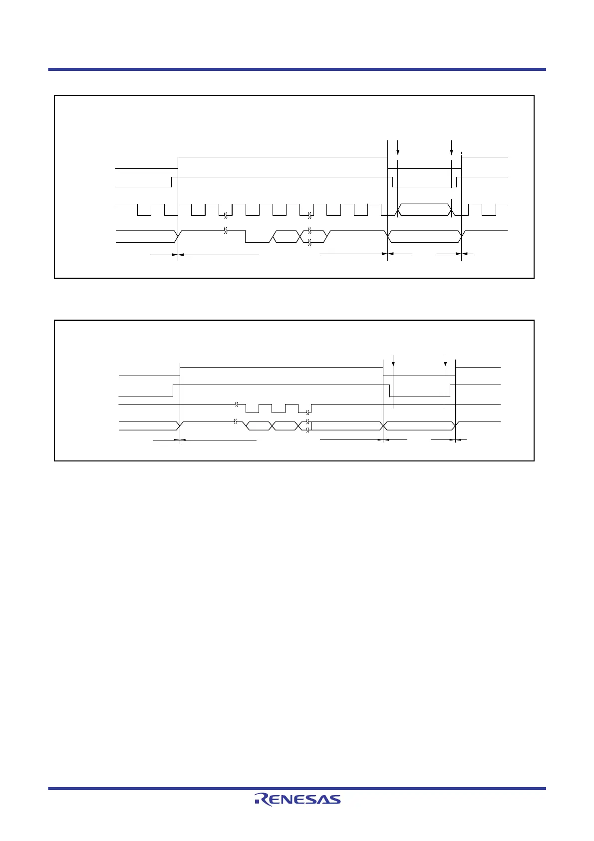
Figure 33.78 Port Pin States during Transition to Software Standby Mode
(Internal Clock, Asynchronous Transmission)
Figure 33.79 Port Pin States during Transition to Software Standby Mode
(Internal Clock, Clock Synchronous Transmission)
Port input/outputPort input/output
High output
Stop
SCI TXDn output
Port
Port
Transition to
software standby
mode
Software standby mode
canceled
SCKn output pin
Port mode register
(PMR) setting
TXDn output pin
SCI TXDn output
SCR.TE bit
The level before transition to
software standby mode is
output
The level at transition to
software standby mode is
retained
Port input/outputPort input/output
Marking output
SCI TXDn output
Port
Port
Transition to software
standby mode
SCKn output pin
Port mode register
(PMR) setting
TXDn output pin
Software standby
mode canceled
SCI TXDn output
Last TXD bit retained
SCR.TE bit
The level before transition to
software standby mode is output

 Loading...


