R01UH0823EJ0100 Rev.1.00 Page 198 of 1823
Jul 31, 2019
RX23W Group 9. Clock Generation Circuit
9.4 Sub-Clock Oscillator
The only way of supplying the clock signal from the sub-clock oscillator is connecting a crystal.
9.4.1 Connecting 32.768-kHz Crystal
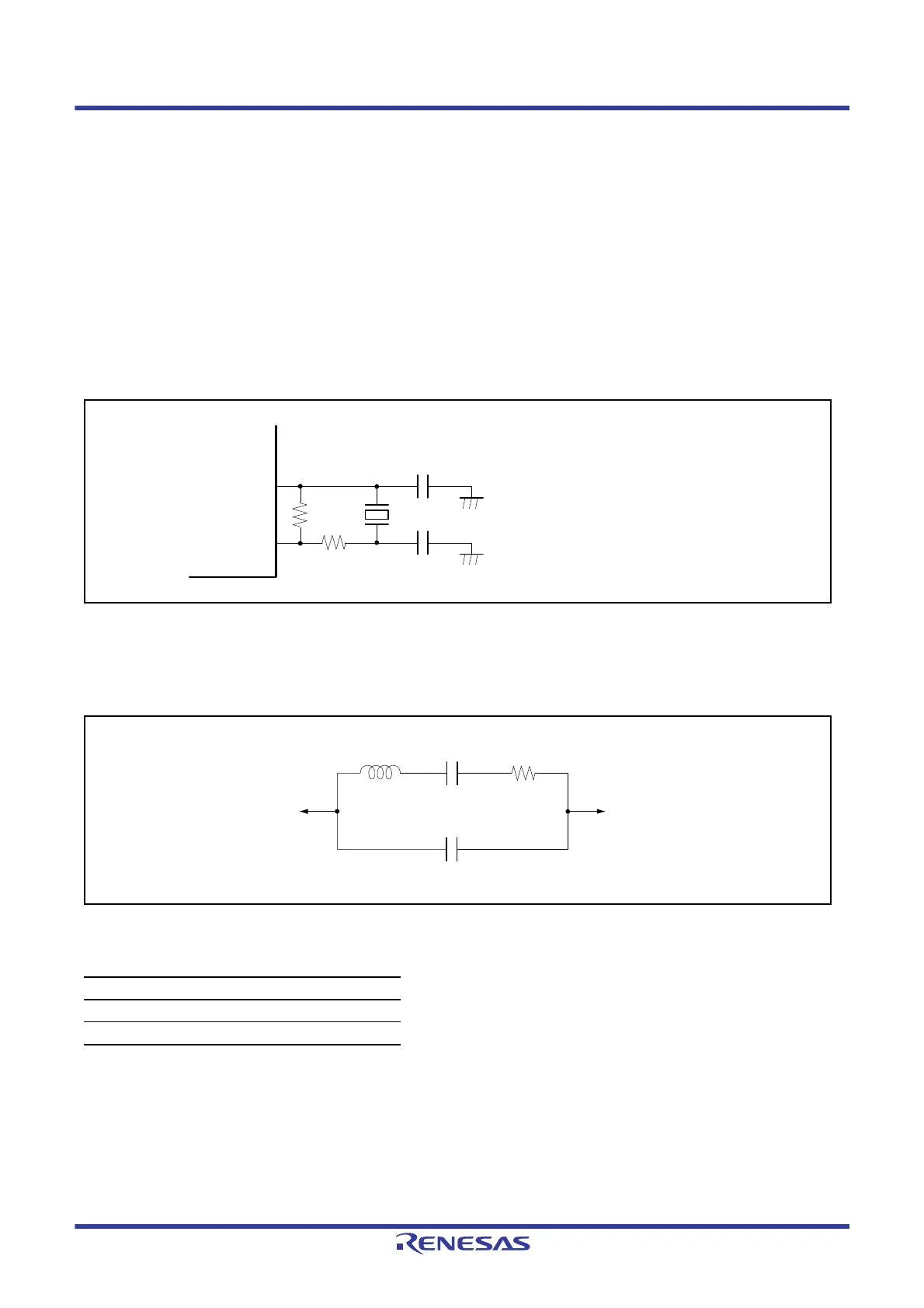
To supply a clock to the sub-clock oscillator, connect a 32.768-kHz crystal, as shown in Figure 9.7.
A damping resistor Rd should be added, if necessary. Since the resistor values vary depending on the resonator and the
oscillation drive capability, use values recommended by the resonator manufacturer. If use of an external feedback
resistor (Rf) is directed by the resonator manufacturer, insert an Rf between XCIN and XCOUT by following the
instruction. When connecting a resonator to supply the clock, the frequency of the resonator should be in the frequency
range of the resonator for the sub-clock oscillator described in
Table 9.1.
Figure 9.7 Connection Example of 32.768-kHz Crystal
Figure 9.8 shows an equivalent circuit for the 32.768-kHz crystal. Use a crystal that has the characteristics listed in
Table 9.6.
Figure 9.8 Equivalent Circuit for Crystal
Table 9.6 Crystal Characteristics (Reference Values)
Frequency (kHz) 32.768 (Low CL)
R
S
max (kΩ) 37
C
0
max (pF) 0.9
XCIN
XCOUT
C1
C2
C1 = 9 pF, C2 = 9 pF (reference values)
Rd
Rf

 Loading...


