R01UH0823EJ0100 Rev.1.00 Page 1086 of 1823
Jul 31, 2019
RX23W Group 33. Serial Communications Interface (SCIg, SCIh)
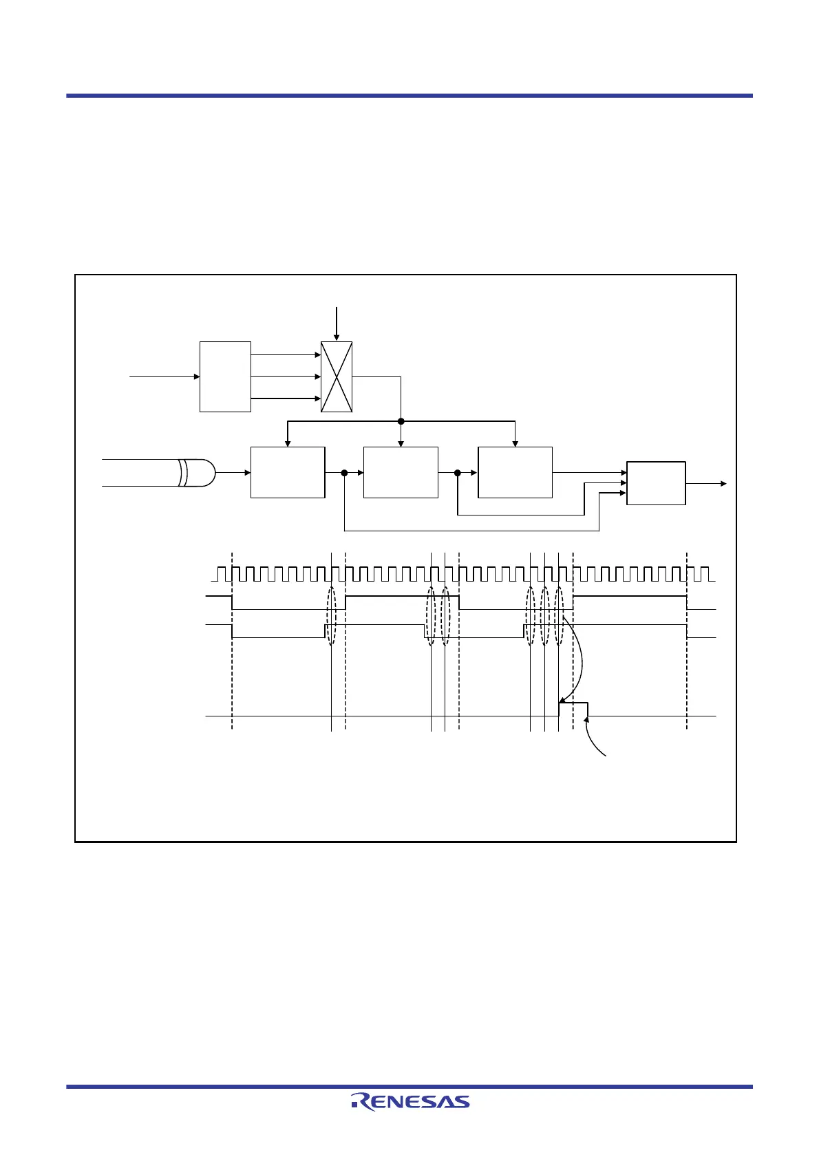
33.10.4 Detection of Bus Collisions
Detection of bus collisions operate for cases where output of the Break Field low width and transmission of data are in
progress when the ESMER.ESME bit and the SCI.TE bit are set to 1.
Figure 33.69 shows an example of operations with bus collision detection. Signals output through TXDX12 and input
through RXDX12 are sampled with the bus collision detection clock set with the CR2.BCCS[1:0] bits as the sampling
clock, and the STR.BCDF flag is set to 1 if the signals fail to match three times in a row. An SCIX2 interrupt is also
generated if the value of the ICR.BCDIE bit is 1.
Figure 33.69 Example of Operations with Bus Collision Detection
D
C
QD
C
QD
C
Q
Base clock
Divider
No division
Division by 2
Division by 4
RXDX12 input signal
Bus collision clock
STR.BCDF
CR2.BCCS[1:0]
Bus collision detection clock
Signals not
matching 3 times
confirms a bus
collision.
Write 1 to
STCR.BCDCL
The above diagram assumes the following:
ESMER: ESME = 1
CR2: BCCS[1:0] = 01b
PCR: TXDXPS = 0, RXDXPS = 0
ICR: BCDIE = 1
Match-
detection
circuit
TXDX12 output signal
RXDX12 input signal
TXDX12 output signal

 Loading...


