R01UH0823EJ0100 Rev.1.00 Page 1414 of 1823
Jul 31, 2019
RX23W Group 39. CRC Calculator (CRC)
39.2 Register Descriptions
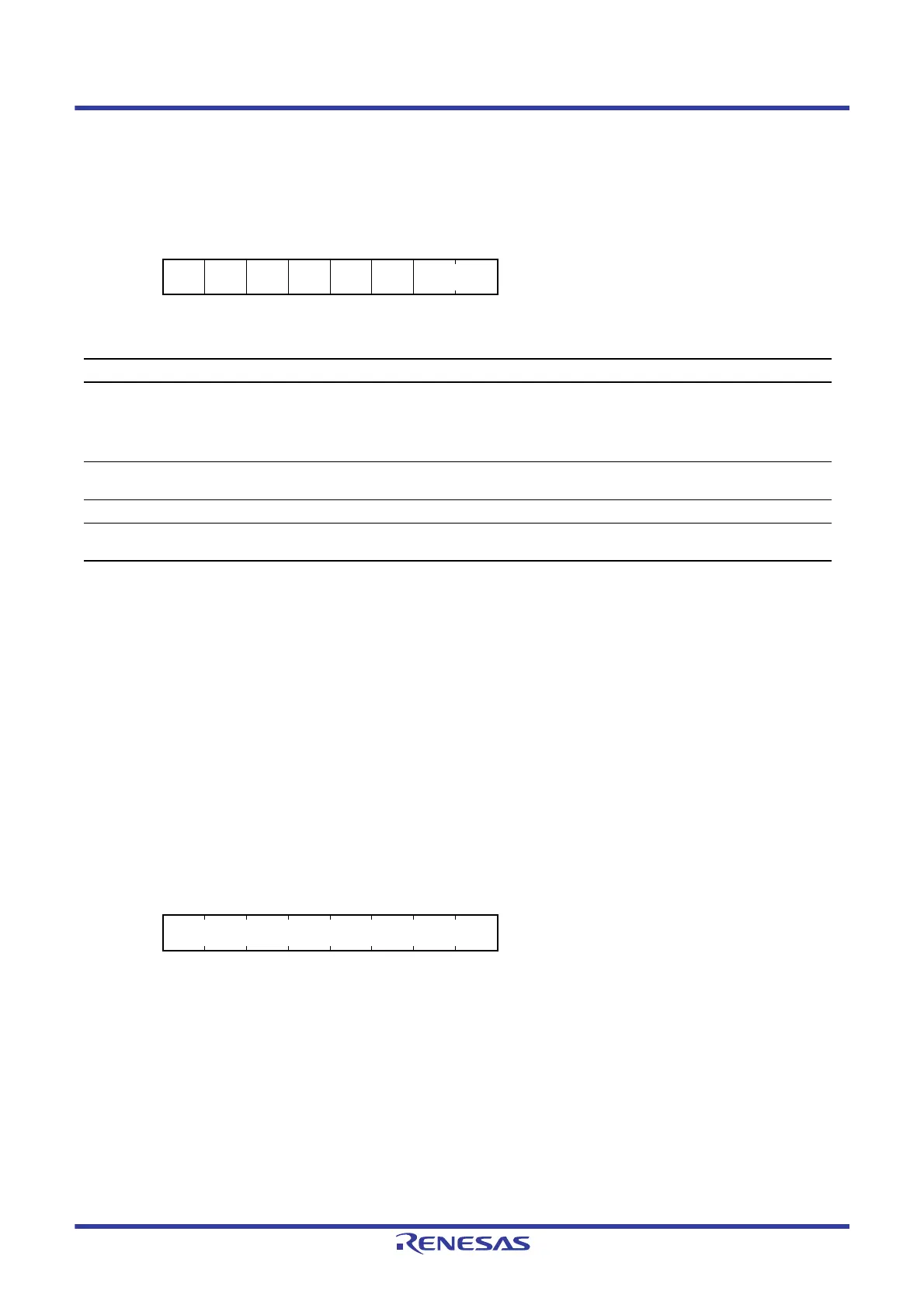
39.2.1 CRC Control Register (CRCCR)
Note 1. Only 1 can be written.
LMS Bit (CRC Calculation Switching)
This bit selects the bit order of generated 16-bit CRC code. Transmit the lower-order byte (b7 to b0) of the CRC code
first for LSB first communication and the higher-order byte (b15 to b8) first for MSB first communication. For details on
the transmission and reception of CRC codes, refer to
section 39.3, Operation.
DORCLR Bit (CRCDOR Register Clear)
Write 1 to this bit so that the CRCDOR register is set to 0000h.
This bit is read as 0. Only 1 can be written.
39.2.2 CRC Data Input Register (CRCDIR)
CRCDIR is a readable and writable register. Write data for CRC calculation to this register.
Address(es): 0008 8280h
b7 b6 b5 b4 b3 b2 b1 b0
DORCL
R
————LMSGPS[1:0]
Value after reset:
00000000
Bit Symbol Bit Name Description R/W
b1, b0 GPS[1:0] CRC Generating Polynomial
Switching
b1 b0
0 0: No calculation is executed.
0 1: 8-bit CRC (X
8
+ X
2
+ X + 1)
1 0: 16-bit CRC (X
16
+ X
15
+ X
2
+ 1)
1 1: 16-bit CRC (X
16
+ X
12
+ X
5
+ 1)
R/W
b2 LMS CRC Calculation Switching 0: Generates CRC for LSB first communication.
1: Generates CRC for MSB first communication.
R/W
b6 to b3 — Reserved These bits are read as 0. The write value should be 0. R/W
b7 DORCLR CRCDOR Register Clear 1: Clears the CRCDOR register.
This bit is read as 0.
R/W*
1
Address(es): 0008 8281h
b7 b6 b5 b4 b3 b2 b1 b0
Value after reset:
00000000

 Loading...


