R01UH0823EJ0100 Rev.1.00 Page 375 of 1823
Jul 31, 2019
RX23W Group 18. DMA Controller (DMACA)
18.5 Interrupts
Each DMAC channel can output an interrupt request to the CPU or the DTC after transfer in response to one request is
completed. When the transfer destination is the on-chip peripheral bus, an interrupt request is generated upon completion
of data write to the write buffer not to the actual transfer destination.
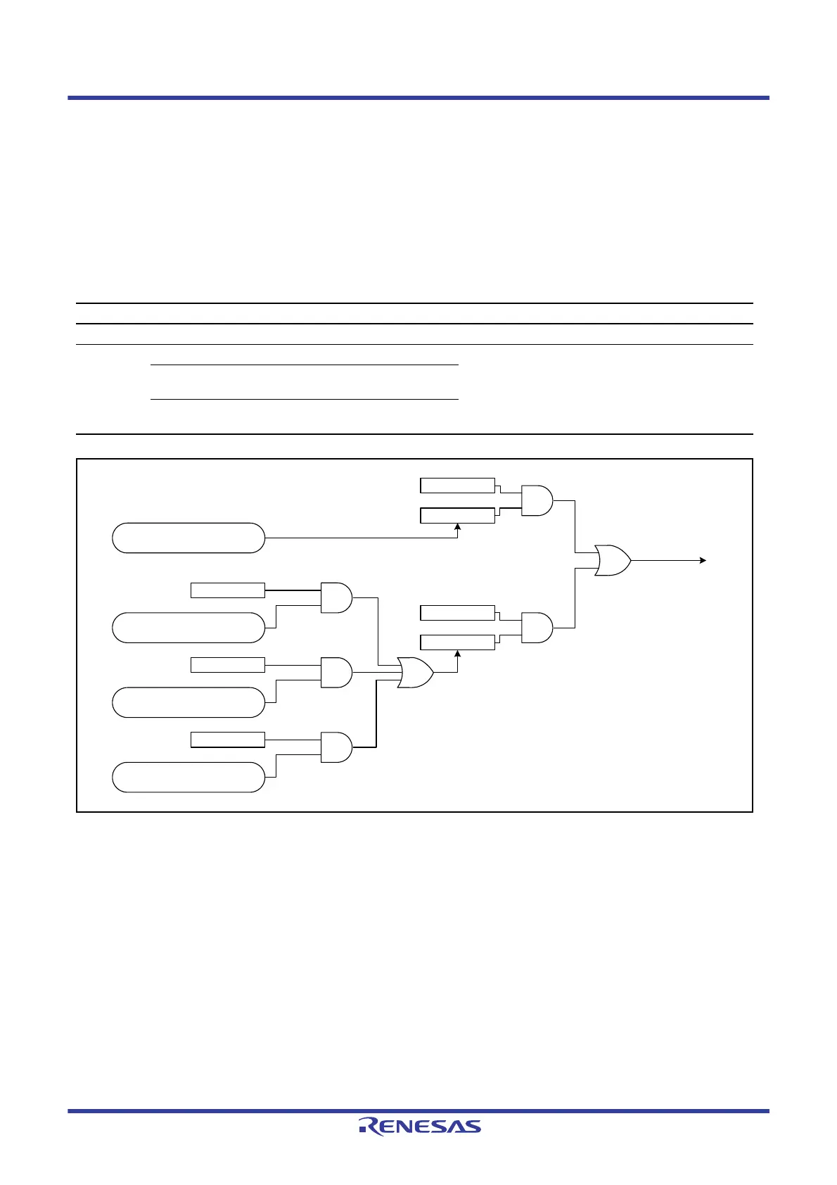
Table 18.8 lists the relation among the interrupt sources, the interrupt status flags, and the interrupt enable bits. Figure
18.13
shows the schematic logic diagram of interrupt outputs. Figure 18.14 shows the DMAC interrupt handling
routine to resume or terminate DMA transfer.
Figure 18.13 Schematic Logic Diagram of Interrupt Outputs
Table 18.8 Relation among Interrupt Sources, Interrupt Status Flags, and Interrupt Enable Bits
Interrupt Sources Interrupt Enable Bits Interrupt Status Flags Request Output Enable Bits
Transfer end — DMACm.DMSTS.DTIF DMACm.DMINT.DTIE
Escape
transfer end
Repeat size end DMACm.DMINT.RPTIE DMACm.DMSTS.ESIF DMACm.DMINT.ESIE
Source address extended repeat
area overflow
DMACm.DMINT.SARIE
Destination address extended
repeat area overflow
DMACm.DMINT.DARIE
RPTIE
When the specified repeat (or block)
size of data transfer is completed
When a source address extended
repeat area overflow occurs
When a destination address extended
repeat area overflow occurs
SARIE
DARIE
ESIF
1-setting condition
DTIF
When the specified number of data
transfer operations are completed
DTIE
ESIE
1-setting condition
DMACm interrupt request
Interrupt output logic diagram for DMAC channel m (DMACm)
m = 0 to 3
 Loading...


